
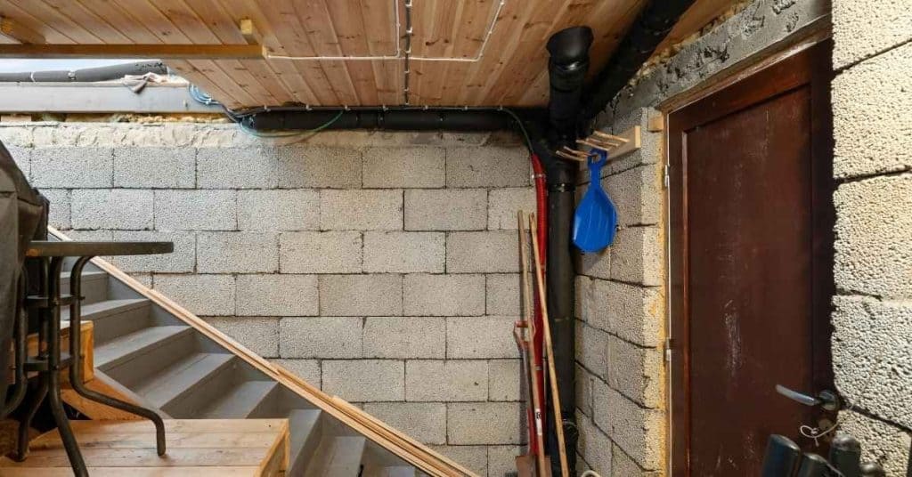
Introduction
This guide is for a small, above-grade, non-load-bearing concrete masonry unit (CMU) wall on a sound, approved base—for example, a low garden or landscape screen wall. It explains layout, mortar work, cutting, joint finishing, and inspection. It is not a structural design guide.
Stop and get code review and, where required, engineered plans for a retaining wall; a foundation or basement wall; a wall supporting a roof, floor, slab, or other load; a tall or freestanding wall; a wall exposed to surcharge, seismic, frost, or hydrostatic-pressure conditions; or a wall tied to an existing structure. The IRC includes specific design requirements for some masonry foundation walls with unbalanced backfill or hydrostatic pressure; see the applicable IRC foundation provisions and your local building official.
Key takeaways
- Confirm permits, setbacks, utility locations, the approved base, wall layout, and block type before buying materials.
- Use nominal block dimensions only for layout; verify the manufacturer’s specified unit dimensions and plan for intended mortar joints.
- Lay the first course on a clean, level base, then build corners first and run a taut line between them.
- Use the mortar, grout, reinforcement, lintel, flashing, and movement-joint details specified for the project—do not substitute generic spacing rules.
- Protect fresh masonry from rain, freezing, excessive heat, drying wind, impact, and premature loading.
Table of Contents
- Introduction
- Key takeaways
- Planning Your Blockwork Project
- Preparing the Site and Foundation
- Materials Needed for Concrete Blockwork
- Essential Tools and Equipment
- Step-by-Step Guide to Laying Concrete Blocks
- Finishing Techniques and Surface Treatments
- Common Mistakes and How to Avoid Them
- Safety, Inspection, and Quality Control
- Conclusion
- FAQ
Planning Your Blockwork Project
Designing and Measuring
Draw the wall to scale before work begins. Mark its length, height, corners, ends, openings, intersections, cap units, and the intended bond pattern. If an opening, bond beam, lintel, flashing, reinforcement, grout, anchor, or movement joint appears on the plan, establish its exact location before mixing mortar.
A common CMU is a nominal 8 × 8 × 16 inches. Nominal dimensions include the mortar-joint module; specified unit dimensions are commonly about 3/8 inch smaller, and sizes vary. Verify the manufacturer’s unit dimensions, thickness, type, ASTM designation, and availability before setting out the wall. The CMHA overview of CMU sizes and specifications explains the distinction between nominal and specified dimensions.
For a simple rectangular wall, calculate gross wall area (length × height), subtract openings only when their dimensions and bond pattern are fixed, and divide the net area by the face area of the specified unit. Add a project-appropriate allowance for cuts and breakage; a 5% allowance is a useful example for straightforward work. Use the selected mortar product’s coverage chart rather than a universal bag count. Complex openings, reinforced cells, bond beams, pilasters, and unusual units need a drawing-based takeoff.
Permits, Codes, and Local Standards
Check permits, property lines and setbacks, utility locations, local frost requirements, soil conditions, wind exposure, and any inspection requirements before excavation. Footing size, depth, reinforcement, and excavation geometry are not universal DIY dimensions; they come from approved plans, code tables, or an engineer.
Cost Estimation and Budgeting
Price the specified blocks, corner/end/half units, mortar, caps, flashing, sealant, and any approved reinforcement or anchors. Include delivery, disposal, tool rental, and weather protection. Keep a contingency for breakage, cuts, site conditions, and delays rather than assuming a fixed percentage will fit every project.

Preparing the Site and Foundation
Excavation, Drainage, and Subbase
Mark the wall line and keep stakes and string clear of excavation. Build only on the base detail approved for the wall. The base must be clean, sound, level, and properly compacted where compaction is specified. Do not assume a gravel thickness, trench slope, drain location, or footing depth from a general guide.
Drainage is especially important for retaining and below-grade work, but those walls are outside this routine DIY scope. Their drainage layer, drain path, waterproofing, backfill, and compaction sequence must match the design. Never backfill a retaining or foundation wall until the required masonry or grout strength, bracing condition, and inspection approvals have been achieved.
Footings and Foundations
For a wall that requires a concrete footing, follow the approved footing detail exactly. It governs dimensions, reinforcement, concrete placement, curing, and the location of starter bars. Do not add rebar, grout-filled cells, or joints based on a generic spacing rule. A masonry movement joint is not automatically the same thing as a joint in a poured footing.
Layout and Batter Boards
Set corner stakes and batter boards outside the work area. Run a taut line for the wall face, then check the layout by measuring diagonals on rectangular work. Mark course heights on a story pole or corner gauge using the actual block module and intended bed joints. Correct layout errors now, not after the first course is mortared in place.
Materials Needed for Concrete Blockwork
Buy the unit type and accessory pieces shown on the plan: standard units plus any corner, end, half, cap, jamb, lintel, or bond-beam units required. Do not substitute or mix hollow and solid units unless the wall design, dimensions, strength, finish, reinforcement, and grout detail allow it.
Mortar, Grout, and Reinforcement
Select mortar by the plans, local code, unit type, exposure, and manufacturer instructions—not by a rule that assigns one mortar type to hollow units and another to solid units. Measure water and use the product’s stated mixing time, working time, temperature limits, and cleanup instructions. Do not rely on “peanut butter” consistency as a substitute for the data sheet, and do not retemper or use mortar outside its permitted working time.
For example, the selected product’s mortar-mix instructions and coverage information control water addition, mixing, bedding, tooling, and curing. Mortar joins units; it is not a substitute for structural grout or reinforcement.
Use grout only in cells identified by the approved detail. That detail must establish grout type, cells to fill, cleanouts, lift heights, consolidation, inspection, and when adjacent work may proceed. Vertical reinforcement, joint reinforcement, bond beams, and lintels are design elements: install them only where specified. Every opening needs an approved lintel or load-bearing detail; a block placed across an opening is not a lintel.
Material Specs and Quality Checks
- Blocks: Reject cracked, badly chipped, contaminated, or dimensionally incompatible units.
- Mortar: Keep bags dry; mix only what can be placed and finished within the product’s allowed working time.
- Reinforcement and anchors: Confirm type, location, cover, and condition against the drawings before covering them.
- Flashing, caps, and sealants: Use compatible materials and install them where the wall detail calls for them.
Essential Tools and Equipment
Hand Tools Checklist
- Mason’s trowel and pointing trowel: for spreading and trimming mortar.
- Jointer and stiff brush: for tooling joints and cleaning fresh smears.
- Spirit level, straightedge, mason’s line, tape, chalk line, and square: for layout, level, plumb, and alignment checks.
- Rubber mallet, masonry hammer, and chisel or splitter: for small adjustments and appropriate manual cuts.
- Mortar tub, hoe or mixer, measured water container, and clean buckets: for controlled batching.
Power Tools and Rentals
- Masonry saw with integrated water delivery: preferred for powered block cutting.
- Approved drill or rotary hammer: only for anchors or holes specified by the wall detail.
- Mixer: useful when batch size and product instructions justify it; clean it before mortar hardens.
- Scaffolding: use only when it is appropriate, fully assembled, level, and protected against falls. Do not work from improvised platforms.
PPE and Cutting Safety
Wear eye protection, hearing protection for powered equipment, gloves suitable for masonry work, protective footwear, and clothing that limits skin contact with wet cementitious materials. Concrete and mortar can irritate or burn skin; wash splashes off promptly.
Cutting, drilling, grinding, and crushing block or mortar can create respirable silica. Mark the cut, use a splitter or manual method where practical, and prefer a masonry saw with continuously supplied water for powered cutting. Work outdoors or in a controlled area, keep bystanders out of the dust zone, manage slurry and electrical hazards, and do not dry-cut indoors. OSHA’s silica standard and Table 1 controls describe task-specific water, dust-control, and respiratory requirements; a generic dust mask is not automatically adequate.

Step-by-Step Guide to Laying Concrete Blocks
Step-by-Step Process
- Confirm the plan. Before mixing, verify the bond pattern, course heights, corner and end units, cuts, opening sizes, lintel detail, flashing, anchors, reinforcement, grout cells, and movement joints. Dry-lay critical areas if it helps confirm the layout.
- Set reference lines. Establish the wall face and corners with batter boards and a taut line. Check square, level, and the base condition. The first course must not be used to hide a badly uneven or unsuitable base.
- Mix mortar to the product instructions. Measure water, mix for the stated time, and make batches small enough to use within the working time. Protect the mix from contamination and do not add water contrary to the instructions.
- Build the first course and corner leads. Spread a continuous bed joint on the approved base. Butter the head joint as each unit is placed. A nominal 3/8-inch joint refers to the intended mortar-joint module; verify the joint requirement for the selected system. Set corner units first, then check level, plumb, line, and course height before filling between them.
- Run each course. Lay intervening units to the line with the planned bond. Fully bed and head-joint each unit, tap it gently into position, and remove excess mortar from the face before it hardens. Check line, level, plumb, and joint consistency every course; lift and reset a badly placed unit while the mortar is workable rather than forcing it into place.
- Make cuts safely. Measure twice, mark the cut, and use the planned half or end unit where possible. For a powered cut, use the wet-cutting precautions described above. Reject a unit cracked by cutting or handling.
- Install specified details as you reach them. Place flashing, anchors, reinforcement, lintels, bond beams, and grout only as detailed. At an intersection, use interlocking masonry or specified ties/anchors. A new wall that merely touches existing masonry is not necessarily structurally connected.
- Tool, protect, and cure. Tool joints when the mortar reaches the product’s recommended stage, often described as thumbprint hardness. Build continuously only within workmanship and product limits; do not wait a universal 24 hours between courses. Protect fresh work from weather and loading, and follow the mortar, grout, concrete, and coating instructions for curing and recoat timing.
Openings, Corners, and Existing Walls
Plan cuts around openings before laying the first course. Build corners and leads first, and use them to control the line and course height. Install jamb details, lintels, flashing, and any specified reinforcement in the sequence shown on the drawings. Do not place a movement joint at a lintel end unless the detail specifically requires it; joint location affects load distribution.
For a connection to existing masonry, first confirm that the existing wall is sound and locate possible reinforcement and utilities. Use designed dowels o