
Table of Contents
- What is a Control Joint Tool and Why Make One from Scrap Steel
- Concrete Joint Standards and Design Requirements
- Materials — Choosing the Right Scrap Steel
- Tools, Consumables, and Safety Gear Needed
- Design Options and Templates (Fixed vs Adjustable)
- Step-by-Step Fabrication: Cutting and Shaping Parts
- Assembly and Welding Best Practices
- Heat Treatment, Hardening and Tempering (When Needed)
- Setup, Calibration, and Field Testing
- Using the Tool Safely and Effectively in the Field
- Maintenance, Sharpening, and Repair
- Troubleshooting Common Problems and How to Fix Them
- Cost, Time, and ROI: DIY vs Buying Commercial Tools
- Repeatable Jigs, Templates, and Batch Production Tips
- Photos, Diagrams, and Downloadable Plans
Introduction
You can make a functional control joint tool from scrap steel by shaping and assembling simple metal pieces.
The article explains how to select appropriate scrap material, plan safe fabrication, and form a precise tool that suits common joint tolerances.
You’ll learn practical steps, tips for measurement and alignment, and rules of thumb to test and adjust the tool in real-world work. Read the safety checklist and the “When to call a pro” list before attempting heat treatment or structural welds.
What is a Control Joint Tool and Why Make One from Scrap Steel
A control joint tool is a simple hand or push tool used to cut or press shallow, precise scoring lines in fresh concrete to guide crack formation and maintain proper joint spacing. It fits into finishing work by creating clean, straight joints just ahead of or alongside the finishing trowel, ensuring cracks follow the intended pattern rather than random paths. Building one from scrap steel can dramatically cut costs, make use of readily available parts, and allow for easy repair or reconfiguration if dimensions or edge profiles need adjustment.
When planning a DIY tool, focus on dimensions that match common slab thicknesses, a durable edge profile that resists chipping, compatibility with standard saws or joint makers, and essential components like scrap steel pieces, fasteners, a comfortable handle, and alignment aids. Outline practical construction steps and tradeoffs, such as selecting appropriate scrap parts, cutting clean edges, fastening securely, testing fit against a joint maker, and marking an optimal grip position for repeatable use. The approach offers customization and repairability, but you’ll trade off some durability and precision versus commercial tools, so prioritize safety, clean cuts, proper joint alignment checks, and mindful handling during fabrication and use.
Purpose and function of control joints
Control joints are deliberate weak spots that force concrete to crack where you want it to, not across your slab or patio. Think of them as predetermined break lines. When the slab shrinks or moves, the crack follows the joint instead of ruining the surface pattern or stepping over doorways.
Place joints based on slab thickness and panel size: a good rule of thumb is spacing in feet = 2–3 times the slab thickness in inches (a 4″ slab gets 8–12 ft panels). Put joints at corners, at door thresholds, and where the slab changes width or load conditions. Don’t float random joints — line them up logically so the whole slab breaks predictably.
Make the cuts deep enough and timely. For saw cuts or formed joints aim for about 1/4 to 1/3 of the slab depth, with cut widths typically around 1/8″–3/8″. Cut early enough to control cracking (often within the first 6–18 hours for typical mixes) but not so early you tear the surface. Check base compaction, avoid placing joints under heavy concentrated loads, and don’t skimp on depth — shallow joints won’t work.
Advantages of DIY vs. commercial tools
Making a control joint tool from scrap steel saves money and lets you tune the tool to your slab and joint size. Below are the actual tools you’ll need on the job, what they do, and when you can skip them or rent instead.
- Angle grinder — Cuts and bevels scrap steel for the joint head. Use a 4–7″ grinder with a metal cutoff wheel or flap disc; choose discs rated for the grinder RPM (typically 10,000–12,000 rpm for 4½” consumer grinders). For steel plate use a 36–60 grit flap disc for stock removal and 80–120 grit for finish; do not use masonry discs on steel.
- Metal-cutting saw — Faster, straighter cuts on square tubing or flat bar. A 14″ abrasive chop saw or cold-cutting abrasive saw is ideal; when cutting mild steel use an abrasive wheel rated for steel or a carbide-toothed blade with 36–60 teeth for 1/8″–1/4″ plate and 60–120 teeth for finer work. Match blade RPM to the wheel specifications on the saw.
- MIG welder — Joins pieces and tacks the guide assembly. For 1/8″ (3 mm) plate, run ~60–80 A; for 1/4″ (6 mm) plate, 140–180 A with proper prep and multi-pass technique. Use ER70S-6 wire for mild steel; flux-core 0.030″ for outdoor non-shielded work. If unsure of amperage for your material, test-weld on a scrap piece and break the weld to inspect penetration or consult a welding chart.
- Bench grinder / hand file — Cleans burrs and sharp edges after cutting or welding. A 6–8″ bench grinder with coarse (~36–60) and fine (~80–120) wheels plus bastard and second-cut files keeps edges true. Avoid overheating: slide the work through the grinder quickly and dip in water frequently for small parts.
- Drill and bits — Drill holes for fasteners or alignment pins in the tool. Use high-speed steel (HSS) or cobalt bits at low speed for steel: ~400–1,000 RPM depending on bit size (slower for large diameters). Pilot drill for holes larger than 1/4″. Use cutting fluid to extend bit life.
- Clamps and vise — Hold parts square while you tack or weld. Bar clamps, C-clamps, and a bench vise with at least 4″ jaws are essential. Skimping here means warped joints and poor fit — clamps are cheap compared to fixing crooked tools later.
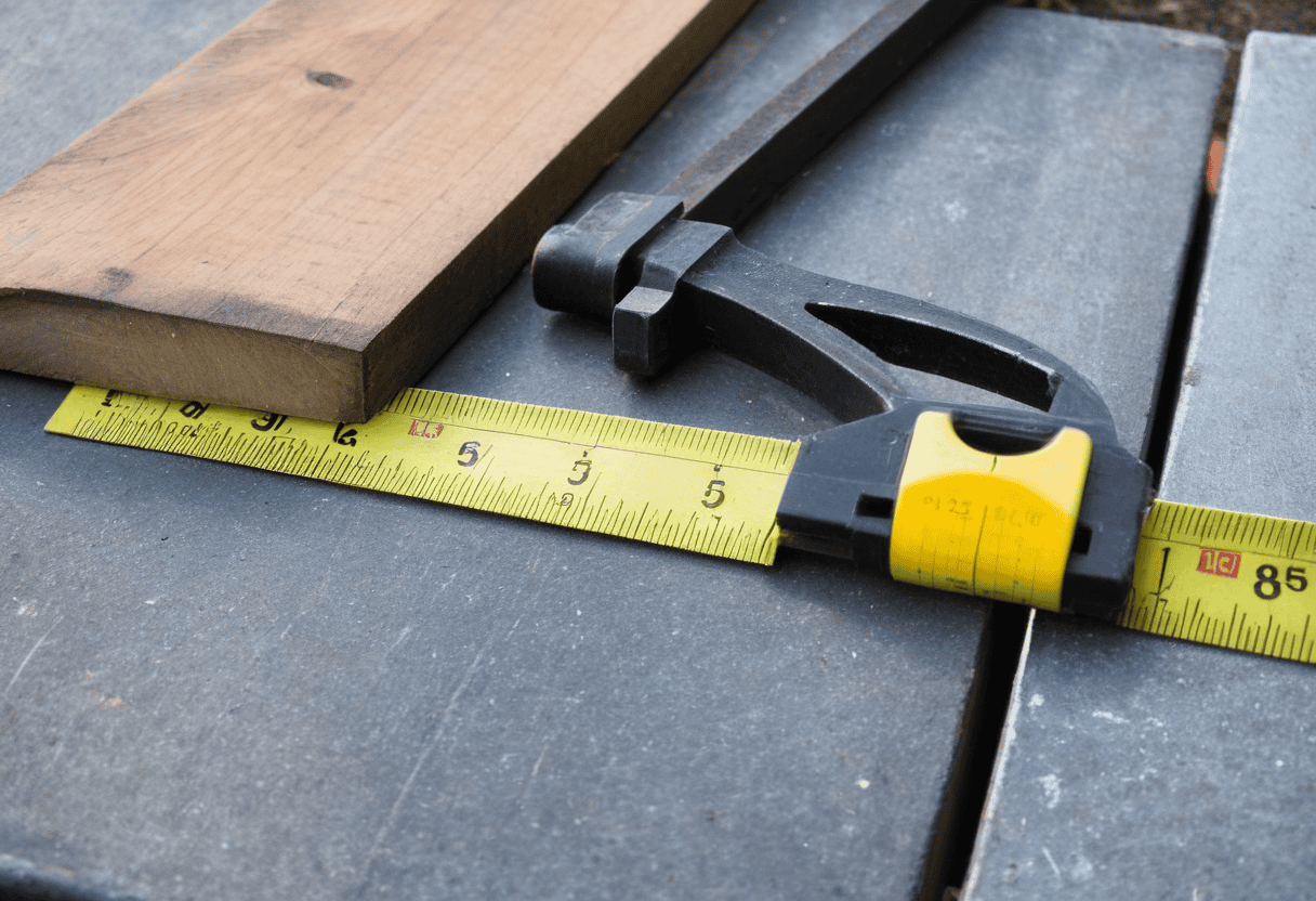
- Measuring and layout — Tape, combination square, center punch, and a permanent marker for layout and alignment. Accuracy to 1/16″ keeps the joint tool cutting straight and at the right depth. Don’t eyeball it; a misaligned tool ruins a control joint line and wastes a slab edge.
- Personal protective gear — Welding helmet (auto-darkening recommended), gloves, safety glasses, ear protection, and respirator for grinding. Good PPE prevents burns, eye injuries, and inhalation of metal dust. Skipping proper gear risks permanent injury and weakens your ability to finish the job.
Pro tip: Combine a grinder and a metal-cutting saw for rough cutting, then finish with a bench grinder and file for fit. Rent the saw or welder for a day if you don’t use them often — you’ll save money and avoid buying tools that sit in the garage.
Concrete Joint Standards and Design Requirements
Concrete joints typically require a groove depth close to one-quarter of the slab thickness, a rule that directly guides the scrap-steel tool’s groove depth during fabrication and helps ensure consistent results on site. Variations occur by slab type—residential, commercial, indoor—and by anticipated shrinkage, which also influences recommended spacing and the target groove position to accommodate movement without compromising performance. Code-relevant recommendations from ACI 302.1R and ACI 360, along with local design codes and frost-heave considerations, set the baseline for joint acceptance criteria and the general design practice you should mirror in the tool. Refer to the latest ACI documents or local authority having jurisdiction (AHJ) for clause references; when in doubt, obtain engineer sign-off for reinforced or commercial slabs.
Your tool design should consistently deliver groove width and depth under changing temperature, moisture, and shrinkage, with features such as adjustable depth control or repeatable cutting cycles to accommodate diverse job conditions. Understanding the differences among saw-cut, formed, and contraction joints helps ensure the groove profile aligns with code requirements and construction tolerances across slab types, so the tool supports reliable performance regardless of method. A concise field snag-check on site—pre-pour layout, template alignment, depth gauge readings, and spacing marks—helps verify readiness before concrete pours and reduces rework.
Typical spacing and depth per slab thickness
Use a simple rule of thumb: joint depth ≈ 1/4–1/3 slab thickness for contraction/sawed joints. Isolation joints (around columns, walls, footings) should go full depth to the subgrade. If you’ve got mesh or rebar near the top, you may need deeper cuts or adjusted joint layout so the joint actually weakens the slab where you want it to.
For spacing, a quick practical formula works on site: spacing in feet ≈ 2–3 × slab thickness (in inches). That gives about 8–12 ft for a 4″ slab, 10–15 ft for 5″, and 12–18 ft for 6″. Reduce spacing for heavy wheel loads, high shrinkage mixes, or poor base conditions. Don’t stretch spans hoping concrete will hold up — tighter is cheaper than patching.
Before you cut or form joints, check base compaction, slab thickness, and any reinforcement that could interfere. Mark your joint lines before pouring if possible. And remember: isolation joints must be continuous to the subgrade; contraction joints only need partial depth as noted. If you’re unsure, err on the side of closer spacing and slightly deeper saw cuts.
Dimensional tolerances and edge radii
Keep joint locations within about ±6 mm (1/4″) of the layout and joint depths within ±6–10 mm (1/4″–3/8″) of the specified depth. If a joint is too shallow you’ll get cracking; too deep and you weaken the slab. Measure with a tape and a simple depth gauge at several points along the length — don’t trust one spot. If locations or depths are out of tolerance, mark them and correct before finishing (saw, grind, or recut as needed).
For edge radii, aim for a radius of 3–8 mm (1/8″–5/16″) on formed or sawed edges. A small rounded edge prevents chipping and helps sealants sit properly; sharp 90° edges spall. Use a radius gauge, coin templates, or a calibrated profile gauge to check the radius at a few random spots. If the radius is too large or small, dress the edge with a grinder or hand tool to get it into range.
Check base compaction and joint alignment before pouring — bad subgrade makes any tolerance meaningless. Record measurements on-site: at least three checks per 3 m (10 ft) of joint, showing location, depth and radius. If more than one check fails, stop work and fix the cause rather than chasing cosmetic corrections later.
Materials — Choosing the Right Scrap Steel
Choosing scrap steel for a hand-built control joint tool hinges on matching edge hardness, ductility, bulk strength, and resilience with what’s available in a scrap bin. Tool steel for a sharp edge, mild steel for ductile shaping, rebar for bulk mass, and leaf springs for built-in resilience each fit different roles; target thickness ranges of roughly 1/8″, 3/16″, or 1/4″ depending on the material, and practical heat-treatment guidance (harden to a hard surface when needed, temper to taste for toughness) helps you plan cuts, stock selection, and initial shaping, while keeping an eye on avoidable work-hardening during fabrication.
Assess hardness expectations and work-hardening risks, and consider corrosion protection through bare steel with oil or wax finishes, or coatings and post-storage strategies to extend life in a workshop. Deburring, edge removal, non-sparking considerations, and compatibility with common joint sizes should guide tool fabrication, while a grinder, files, and a basic heat-treat setup keep iterations practical. Sourcing and quality checks should note signs of fatigue or cracks and document substitutions that stay within safe margins for DIY projects.
Steel grades and pros/cons
Mild steel is cheap and easy to cut, weld, and shape. Use it for bodies, frames, and shims where toughness and weldability matter more than a razor edge. It dents before it breaks, so it’s forgiving for DIY work. If you need a sharp edge or wear resistance, mild steel is the wrong choice.
Hardened tool steels hold an edge and resist wear. Use them for blades and wear surfaces. They need heat treatment and careful grinding. If you can’t heat-treat or temper it properly, you’ll end up with a brittle piece that chips or cracks. Check hardness and buy known grades whenever possible.
A quick rule: use mild steel for structure and parts you will weld or bend; use hardened or tool steel for cutting edges and long-wear pieces. Avoid unknown scraps that look plated or have pitting—those can hide cracks or brittle layers. When in doubt, cut a small test piece, heat-treat if needed, and try to grind it before committing to a full part.
Sourcing scrap and required dimensions
Buy from reputable yards, fabricators’ offcuts, demolition sites, and machine shops—these are the common sources that actually have usable pieces. Ask the yard to let you see the cut list or walk the piles; don’t take someone’s word. If you need predictable material for welding or load-bearing parts, stick to supplier stock rather than random demo pieces.
For most small projects I work on, aim for a minimum dimensions of about 24 inches long, 3–4 inches wide and 1/8 inch thick as a practical baseline; thicker for structural parts (1/4″–3/8″). Smaller bits are fine for brackets and trim but waste your time if you need to plate or machine. If you’ve already chosen a grade earlier, match the size to the part loads—not the other way around.
Inspect every piece before you buy: run your hands and an angle grinder along welds and edges to look for hairline cracks, deep pitting from rust, and blue/black surface scale that indicates past overheating. Reject pieces with visible cracks, excessive section loss, or hard, welded-on mill scale—those will bite you later. If in doubt, scrap that one and move on; cheap bad steel costs more time and headaches than paying a bit more for clean stock.
Tools, Consumables, and Safety Gear Needed
A clear inventory of essential shop tools, consumables, and PPE is the backbone of scrap steel projects. Expect a core set of cutting and shaping tools (cutting tool, grinder, drill/driver, clamps, square, tape measure, marker) plus basic specialized items (hammer, mallet, wire brush, file) and a plan that matches scale, angles, and joint specifics to guide material choice and power needs. Include key consumables and fasteners (wheels, discs, gloves, lubricants, rust inhibitor, welding tips or filler rods, zip ties or magnets) and a simple storage idea to keep spent materials organized, along with a targeted PPE checklist for each task phase.
This setup matters because it helps you work safely and efficiently, reducing guesswork when you’re on a tight schedule or a limited setup. It also supports quick adjustments and maintenance, such as tracking blade or disc life and keeping tools clean and corrosion-free. A practical plan for alternatives and maintenance—budget substitutes, rental options, and a short upkeep routine—keeps the project moving when resources are scarce and extends tool longevity on scrap steel jobs.
Shop tools and consumables
These are the actual tools you’ll use every day on the job. I list what each does, when you can rent instead of buy, and a short jobsite tip so you don’t wreck parts or yourself.
- MIG/TIG welder — Joins metal cleanly for frame and repair work. Choose MIG for speed and ease (gas-shielded, 110–240V) or TIG for thin/detailed welds; pick machine amperage to match material thickness. For example: 1/8″ plate ≈ 60–80 A (MIG), 1/4″ ≈ 120–180 A (MIG) with multi-pass. Preheat >3/8″ or for carbon problems. Renting is fine for one-off jobs; cheap or undersized units make weak welds and can crack parts when stressed.
- Angle grinder — Cuts, grinds, and cleans welds fast. Use a 4½–5″ grinder for general work; select flap discs or cutoff wheels rated for steel and the grinder RPM. Discs: 36–60 grit for stock removal, 80–120 for finishing. Always use the guard and proper PPE.
- Cut-off saw — Makes straight metal cuts quickly. Use abrasive wheels rated for steel or a cold-cutting carbide blade. For 1/8″–1/4″ plate a 36–60 tooth carbide blade gives a clean cut; match tooth count to material thickness. Rent if you only need it once; using the wrong blade burns or binds the cut and can ruin the piece or kick back dangerously.
- Drill press — Drills square holes and reams accurately. Use Cobalt or HSS bits for steel; feed and speed vary by diameter (e.g., 1/8″ bit ≈ 1500–2000 RPM, 1/2″ bit ≈ 300–800 RPM). Clamp the work and use cutting fluid.
- Hand files — Smooth edges and fine-fit parts by hand. Keep a selection (flat, round, half-round) and use with steady strokes; files last much longer if you clean them often.
- Clamps and vices — Hold parts square for welding and assembly. Have pipe clamps, C-clamps and at least one decent bench vice; exactness beats brute force.
- Measuring tools — Tape, combination square, calipers and a level for layout. Use calipers for critical fits, and a mag-level or machinist square for alignment.
- Filler materials — Welding wire, rods, and filler metal matched to base metal. Match grade (ER70S for mild steel); store dry rods and spools. Buying the wrong filler or wet rods will make brittle, porous welds that fail under load; buy correct grade or consult a supplier.
Pro tip: Assemble a small kit of the essentials (angle grinder, clamps, measuring tools, weld wire) and rent heavy gear like a cut-off saw or TIG unit when needed. Mixing a decent midrange tool with the right consumables beats owning low-grade tools that cost you time and ruined parts.
PPE and safety preparations
Before you touch any metal or power tool, suit up. Put on a respirator rated for fumes or dust, a welding helmet with the right shade, eye and ear protection, and heavy work gloves. If you already saw the tools list, this is the practical check: make sure the respirator seals, the helmet lens is clean and the ear protection actually blocks noise. Replace or tighten anything that feels loose — don’t improvise with sunglasses or garden gloves.
Control the air and energy. Work where you can check ventilation — open doors, use a shop fan or an air mover, and set a local exhaust or fume extractor close to the source when welding or grinding. For equipment with stored energy, do the simple step: lock out and tag out the circuit or machine. If you can’t lock it, don’t work on it. Period.
Think about the sparks and flying debris. Angle grinders and welders throw hot stuff; shield nearby combustibles and give people outside the immediate work area warning or barriers. Keep a fire extinguisher in reach and a bucket of sand if you’re working outdoors near dry material. If you don’t respect sparks and fumes, you’ll regret it — wear your PPE, control the ventilation, and follow basic lockout/tagout and hazard controls before you start.
Design Options and Templates (Fixed vs Adjustable)
This section compares fixed-width blade designs with adjustable heads and depth-stop systems, outlining in detail how each layout affects stability, repeatability, ease of manufacture from scrap steel, and the likelihood of warping or drift under typical site conditions. It covers material choices, blade length, mounting geometry, edge treatments, friction concerns, and practical trade-offs between accuracy and setup time, plus how each design interacts with common forms, fasteners, and alignment references. Real-world use cases map out where fixed, adjustable, or hybrid configurations excel, where cutting precision and speed matter most, and how imperfect clamps or misaligned templates can undermine performance.
It also ties in templates and jigs, showing how printable or craft-ready profiles can align with formwork to ensure consistent blade engagement across joints and enable rapid repetition on multiple openings. You’ll learn practical steps for setting and locking depth, calibrating against common joint widths, preventing over-cut through simple measurement tricks, and choosing clamps or locks that resist slippage during concrete cutting. Maintenance guidance on inspection cadence, re-sharpening or re-lapping scrap components, protective coatings, corrosion resistance, and safe storage helps you plan for longevity and safer handling on the jobsite.
Printable template and dimensional plans
Make a full-size printable template on cardboard or heavy paper to transfer the critical lines to the site. Print at 1:1 when the slab fits on a sheet, otherwise use a clear scale (1:10 or 1:20) and note the scale on the template. Mark corner points, centerlines, the exact slab edges, and the location of any openings or steps. Add arrows showing finished slope (typical: 1/8″–1/4″ per foot) so the contractor or you know which way to pitch the surface.
On the drawing, label slab thickness and reinforcement for the job. Typical recommendations: shed pad 3″–4″ concrete on compacted base, patio/sidewalk 4″ with 6×6 W1.4xW1.4 welded wire or fiber, garage 4″–5″ with either wire mesh or #3 rebar at about 18″ o.c., driveway 4″ for light cars, 5″–6″ for heavier loads. Put control-joint locations on the template; for a 4″ slab sketch joints about 8–12 ft apart (shorter for irregular shapes).
Also mark base requirements: depth of crushed stone (usually 4″–6″), compaction notes, where to check base compaction, and any drainage/under-slab penetrations. Before pouring, lay the template on the compacted base, drive stakes at the corners, and transfer knock-out locations and joint lines with chalk or spray paint. If you skip this step, expect wasted concrete and awkward saw cuts later.
Downloadable full-scale PDF/CAD templates, a detailed cut list, and a 1-page quick reference (cut list, hole locations, bolt sizes, and recommended weld sizes) are provided in the Photos, Diagrams and Downloadable Plans section. These include: exact cut lengths for a basic hand tool, bolt hole positions with center-to-center values, recommended bolt sizes and torque values, and weld sizes (see the Build Plans summary below).
Adjustable-joint design elements
If you want joints that let you tweak width or depth after installation, build in a few simple adjusters where the parts meet. Use thin shim stacks behind the joint faces to change clearance in small increments, and lock them with set screws or lock nuts. Sliding guides—milled channels or surface-bearing strips—give you smooth travel when you need to open or close the gap regularly.
Decide up front how often you’ll adjust. For a one-time tweak, shims and a couple of set screws are cheap and foolproof. For regular adjustments, spend the extra time on proper sliding guides and captive fasteners so nothing rakes out or jams. Whatever you choose, make sure the adjustment hardware is accessible from the front or side so you don’t have to disassemble the whole assembly.
Before you finalize the layout, cross-check those adjusters with your template or dimensional plan from earlier. Check base alignment, try the full travel by hand, and tighten only once the movement is smooth. If a joint binds, rip out the shim and start again—don’t force it and expect the set screws to fix sloppy fits.
Step-by-Step Fabrication: Cutting and Shaping Parts
Cutting and shaping parts from scrap steel is tackled step by step, with clear goals for material, exact dimensions, tolerances, and blade geometry to ensure reliable joint formation. Start by identifying scrap grades and thickness, then map exact dimensions, tolerances, and profiles, while outlining a safety checklist for DIY fabrication that covers gloves, goggles, hearing protection, and a plan for labeling parts to prevent mix-ups. Next, mark and cut using appropriate methods, deburr thoroughly, and begin shaping the blade or profile with careful attention to heat-treat considerations where applicable, plus plan for clamping and securing parts to maintain straight, repeatable cuts, and note expected deviations.
Plan for preparation and safety on a stable workbench with PPE, proper clamping, and careful handling of sharp edges to prevent injuries at every stage, and set up a dedicated area for marking, cutting, and filing. Compare cutting options—bandsaw, cutoff wheel, or plasma—and factor in kerf, chip removal, wheel wear, feed rate, and the need to cool parts between cuts to control heat-affected zones and preserve tool life. Final finishing and assembly readiness cover edge rounding, flattening checks, alignment with the guide, surface prep, and the prep work needed before use in concrete, including test fits and double-checks against the plan.
Step-by-Step Process
This sequence gets you from a marked blank to ready-to-fit parts. Follow the order, check the quick signs, and don’t rush the cure or clamp times.
- Lay out and verify your measurements on the material using a square and straightedge. Doing this first prevents a costly mis-cut later; check lines for straightness and two opposite dimensions for match. If measurements contradict or you can’t get a repeatable mark, stop and ask for a second opinion — mistakes here ruin parts.
- Choose and inspect the correct blade or bit for the material, then mount it securely. The right tool reduces tear-out and keeps edges true; a loose blade or wrong tooth count shows chatter or burning on the first test cut. For metal saw blades, 36–60 teeth for plate up to 1/4″ give a good balance; higher tooth counts for thin sheets reduce burr.
- Clamp the workpiece to a stable surface and set a fence or guide for the cut. Clamping keeps the part from shifting and gives repeatable cuts; you should hear solid contact and the piece should not move when you try to wiggle it. If you can’t get a secure clamp or the piece flexes, stop and either add supports or call for heavier fixtures.
- Make a shallow practice pass or relief cut along the waste edge before the full cut. A light pass confirms alignment and cutter behavior; the cut should follow the line with minimal tear-out. If it jumps off the line, correct alignment and re-test — don’t force the full-depth cut until it tracks cleanly.
- Complete the full cut or rout in steady, controlled feeds. Keep speed uniform so the edge stays true; check the cut edge for consistent width and no burning or chipping. If the edge shows melted material, delamination, or severe chipping, stop and reassess tooling or feed rate — consider a pro if the material is expensive or safety is at risk.
- Deburr, sand, or file to final dimensions and shape, then dry-fit parts together. This shapes mating faces for good contact and fit; fingers should feel a continuous surface and parts should align without force. If gaps persist after careful sanding or the piece breaks under light pressure, consult a fabricator before applying adhesives or finish.
- If using adhesive, clamp per manufacturer specs and respect cure time; if welding or brazing, do tack, fit, then weld. Proper bonding at this stage locks geometry and strength; quick checks are a clean visible joint and no movement after initial clamp. Never rush cure — follow stated clamp and cure times (often 30 min–24 hrs for adhesives) and call a professional if you get structural weld failures or unusual cracking.
Pro tip: Always do a final square/measurement check before finishing or painting — once adhesive or finish is applied, fixing a mis-cut is much harder and more expensive than re-cutting raw stock.
Cutting and profiling the blade
Mark the profile clearly on the plate and clamp it tight. Choose your tool based on thickness and access: angle grinder for small trims and bevels, plasma for faster, cleaner profiles on medium plate, oxy-fuel for very thick sections. Cut a few millimeters outside the line so you can finish to fit. Leave extra material—never try to cut the final edge dimension on the torch or plasma.
When forming the bevel and edge, rough-cut the angle and then dress it with a flap disc or belt grinder to the final bevel. Check the bevel angle with a protractor or simple jig as you go. Keep cuts steady and remove heat between passes to keep the blade flat. If using oxy or plasma, watch for heat distortion and correct it by light hammering or straightening before final grinding.
After profiling, deburr and clean the mating faces so welds sit flush. Do a dry fit to the joint and check alignment and edge sharpness. If the piece will be welded, grind the weld prep to the specified root gap and bevel measurement rather than guessing—measure twice, cut once. And for safety: PPE, proper clamps, and a fire watch are not optional.
Machining and edge finishing
After you rough-cut and profile the parts, stop and clamp the piece solid. Use a grinder to remove high spots fast, then switch to a coarse file to flatten and a finer file or flap wheel to blend. Work in short passes and check fit frequently against the mating surface — it’s easy to take off more metal than you think.
For edge radius, aim for a consistent small curve that lets parts seat cleanly without sharp corners. Start with a coarse abrasive to establish the radius, then step down grits until the edge is smooth. Use a straightedge and a few light passes with a flat file to confirm straightness along the length; a bowed or wavy edge makes clean joints impossible.
Keep an eye on heat from grinding; stop and cool or you’ll ruin temper and alignment. Deburr only enough to remove burrs and high edges — don’t round away mating faces. If a joint still gaps, back up to the grinder and remove metal where it actually contacts, not where the eye thinks it does. Bad habits now mean poor fit later.
Assembly and Welding Best Practices
Assembly and welding best practices revolve around a well-planned workflow: set up a clean, well-lit workspace with full PPE, prep parts by removing oil, rust, and paint, and secure scraps firmly while labeling pieces; establish the weld sequence before touching metal, then place initial tacks at corners to verify squareness, progressively tighten gaps, and use jigs or fixtures to hold alignment as heat is applied and joints progress toward full-penetration or cosmetic welds with balanced heat input to minimize distortion.
This approach matters on the jobsite because it reduces rework, improves joint fit, and protects structural integrity while keeping warpage under control through heat management, backer bars or heat sinks, staggered passes, and consistent travel speed; it also emphasizes inspection, dry fits, gap measurements, and cleanups to ensure joints stay true during final finishing and coating, so you can trust the welds to perform under real-use conditions.
Jigs and fixturing to prevent distortion
Build a simple, rigid jig that holds parts where they will sit in the final assembly. Use square, solid reference points and clamp both faces if possible. If the piece is thin, add backing bars or a sacrificial plate under the weld path to spread the heat and keep things flat. check alignment before tacking — once welded, it’s much harder to fix.
Tack in a balanced pattern. Start with small tacks opposite each other, then expand outward in a mirror pattern. That stepwise tack sequence reduces pull from one side and keeps the part centered. Don’t do long continuous tack lines; short ones let you adjust as you go.
Plan your weld order and clamps so you can relieve heat as you go. Weld short runs, cool with air or water if necessary, then re-check the jig and clamp points. If distortion appears, stop and add a clamp or tack on the opposite side before continuing. These are practical fixes you can do on the spot — no fancy gear required.
Fastening alternatives and replaceable parts
When a part wears out often, plan to bolt, not weld. Bolts let you swap blades or wear plates with basic tools and minimal downtime. If the item only sees occasional service, welded joints are stronger but kill the ability to replace the part without cutting and rewelding — which you don’t want on a consumable blade.
Design the replacement area for easy access. Give room for a wrench and clearance to back the bolt out. Use captive nuts, welded studs, or slotted holes to help with fit-up in the field. Match bolt grade to load and protect threads with grease or a simple thread locker if vibration is an issue.
Standardize the parts. Use consistent hole patterns, thicknesses, and fastener sizes across machines so spares are interchangeable. Mark torque values and part orientation right on the drawing or the part. If you weld something for strength, make the wear surface a bolted-on sacrificial plate so the whole assembly doesn’t need cutting when the edge wears out.
Heat Treatment, Hardening and Tempering (When Needed)
Heat treatment can improve wear life for blade components made from medium- or high-carbon steels, but it introduces risk (warping, cracking, burned metal, toxic fumes) if done incorrectly. The following guidance is deliberately conservative and intended to help you decide whether to proceed or hire a pro. If you are inexperienced with oxy/acetylene or torch quenching, or your part is a critical safety/structural component, stop and take the part to a qualified heat-treat shop.
When to heat treat (do not heat treat unless required)
- Heat treat only knife/wear edges made from known medium/high carbon steels (e.g., 1045, 1095, 52100, A2, O1). Do NOT attempt with unknown or plated material.
- If the part is structural, thin (<1/8″) or has complex geometry, seek professional heat-treatment services.
- If you cannot identify the steel or test a small sample, do not harden—use a bolted-on replaceable wear plate instead.
Safe, practical DIY hardening summary (for known steels only)
Use this only on small, simple parts made from a known grade. For common grades, approximate a safe starting point (always confirm with small test pieces):
- 1045 (medium carbon): austenitize ~820–860°C (1500–1580°F); quench medium oil; temper 350°F (175°C) for toughness.
- 1095 (high carbon): austenitize ~760–800°C (1400–1475°F); quench oil; temper 400–450°F (200–230°C) to reduce brittleness.
- O1/A2 (tool steels): require accurate heat control—prefer pro treatment. If DIY, follow supplier guidance and expect multiple tempers and controlled cooling.
Typical DIY quench media: oil quench (commercial quench oil preferred). Avoid water quenching for thin blades unless you understand the risks—water cooling frequently causes cracks and severe warpage on small parts.
Step-by-step safe process (small test piece first)
- Clean the part to bright metal; remove paint, scale, grease.
- Clamp or rest the part so it can be heated evenly—support both sides.
- Heat with a propane/oxy torch evenly until non-magnetic or to the target color/temperature. Use a thermocouple if available.
- Quench immediately and smoothly in oil (commercial quench oil preferred). Withdraw straight—avoid slamming or twisting the blade.
- Remove scales and degrease, then temper in a conventional oven at the chosen temper temperature for 1 hour per 25 mm thickness (double cycle recommended: heat, cool to ambient, repeat).
- Test with a file and small bend tests; if it flakes/chips, temper higher/longer or consult a pro.
Quench media and risks
Quench choice and technique matters: water = fastest cooling, largest risk of cracking and warpage; oil = moderate cooling, common DIY choice; polymer quench (e.g., PQ) = cleaner and safer but follow manufacturer instructions. Never use open buckets of unknown fluids—use purpose-made quench oils in a safe, ventilated area and follow local hazardous waste rules for disposal.
Testing and when to stop
Always harden a scrap sample first. Test hardness with a file, Rockwell if available, or a comparative hardness tester. If you see hairline cracks, catastrophic warpage, or chipping on the test piece, do not proceed—seek professional heat treat. If in doubt at any step, stop and consult a professional heat treater or experienced machinist.
Clear safety warnings
- Heat treatment involves hot oil, flammable vapors, and potentially toxic scale—work outdoors or in a ventilated area, wear PPE, and have a fire extinguisher ready.
- If you cannot positively identify the steel, do not attempt to harden it.
- If an edge or blade is a structural or safety-critical part, use professional heat treatment and welding services.
Professional route
For any doubt—unknown alloys, parts thicker than 3/8″ (10 mm), odd geometries, or when meeting certified hardness or toughness is required—send parts to a commercial heat treater. Costs are modest relative to the risk of part failure on site.
Setup, Calibration, and Field Testing
Setup, calibration, and field testing revolve around defining an exact joint depth, width, and alignment reference—centerline, edging, and slab thickness—and then transferring those measurements to a scrap-steel tool for repeatable results on the jobsite. The setup workflow covers securing the tool to the slab form or surface, establishing a consistent baseline, and selecting appropriate drill bit, blade, or notch dimensions to match the chosen joint profile, ensuring stable contact and predictable cut depth. Calibration ensures depth stops, width gaps, and parallelism are within tolerance, while a quick check for wear, burrs, and smooth edges keeps the tool performing reliably before any test cuts are made and any adjustments recorded for traceability.
Field testing uses representative test panels or slabs to mirror real work conditions and standardizes the number of test cuts, concrete mix variations, and measurement methods for depth, width, and notch alignment. Documented results drive iterative tweaks, guiding adjustments to setup, calibration, and tool wear as needed while storing observations in a simple log and flagging safety checks and maintenance tasks for the scrap-steel tool. This phase matters because consistent joints reduce risk of failure, improve finish quality, and minimize rework on actual pours.
Calibrating depth and width stops
Start by picking a reliable reference face on your tool or jig—one flat edge you’ll always measure from. Set the depth stop so the cutter just touches the work on that reference, then back it off the exact amount you want for the finished joint. Use a straightedge and a feeler gauge or a known-thickness shim to verify the gap; don’t trust a ruler held at an angle.
For measurable acceptance criteria: depth tolerance ±6 mm (±1/4″) from the target; width tolerance ±2 mm for narrow joints (<6 mm) and ±4 mm for wider joints. Re-calibrate after every 30–50 linear feet of sawing or every 2 hours of continuous use—whichever comes first—or immediately if you notice drift in cut quality.
Shim to the final dimension between the cutter and fence, clamp the shim in place, and lock the fence. Make a test cut on scrap, measure the actual joint with calipers or a gap gauge, and adjust the shim or stop until the test matches the spec. After dialing in, torque all locks and run three more tests spaced along the workpiece to confirm repeatability. Re-check after the first few real cuts because bit wear and settling or loose clamps will change dimensions.
Testing on sample slabs and interpreting results
Cut a few short trial joints on a spare slab or an out‑of‑the‑way corner before you touch the main work. Run the same setup you plan to use, then look for a clean, full‑depth cut with sharp edges. If the cut flakes, leaves feathered edges, or pulls chunks out, your blade or depth setting needs changing. Check base compaction and the concrete surface — a loose base or soft top will show immediately as broken or pitted edges.
Good joints are straight, even in width, and sit flush with no large voids or jagged lips. Poor joints show tearing, oversized chips, or a gap between the joint and the filler. Also watch for heat damage: discolored or glazed edges mean the blade is too slow or the feed is too aggressive. Press a finger into the joint filler (when cool) — a tight fit that resists light pressure is what you want.
If adjustments are needed, tweak one thing at a time. Back off depth slightly if you pull chunks. Slow the feed or raise blade RPM if the edge is tearing. Increase width incrementally for wider fillers. Replace a dull blade rather than overcompensating with slower passes. After each change, cut another small test—repeat until you get consistent, clean joints before moving to the whole slab.
Using the Tool Safely and Effectively in the Field
Using the tool safely in the field starts with wearing proper PPE—eye protection, gloves, hearing protection, and sturdy boots—while staying mindful of hazards unique to field work such as dust clouds, tripping over cords or debris, and overhead obstacles, and it hinges on a disciplined setup that secures the scrap-steel tool, verifies perpendicular or follow-the-grain guidance where required, and confirms depth control to avoid over- or under-cutting. Practitioners should choose the appropriate scoring versus sawing approach for each joint, maintain a controlled rhythm with deliberate passes to minimize chipping and slag, apply approved lubricants or coolants if applicable, and protect adjacent slab edges and forms through careful lead-ins and lead-outs and by managing blade wear through proper cutting technique.
This method helps minimize tool and slab damage by offering strategies to prevent blade edge damage, reduce vibration-induced cracking, and handle curved sections or edges near forms with gradual navigation, while emphasizing field-ready maintenance such as rust prevention for scrap steel, thorough cleaning, temporary storage, inspection intervals, and quick on-site repairs to extend tool life. Why it matters for DIY and jobsite crews is that following these practices lowers downtime, keeps cuts more accurate and consistent, reduces rework, and improves safety on diverse sites, from tight interiors to open slabs, so you can complete projects more efficiently without sacrificing quality.
Cutting technique and speed recommendations
Keep the machine moving at a steady pace. A jerky or stop-and-go feed makes ragged edges and burns the blade. Aim for a consistent feed rate you can hold for the whole cut—slow enough to let the blade bite, fast enough to avoid overheating. For hand groovers use scoring passes at 2–4 mm depth before final pass; for saws use 2–3 passes for deep grooves rather than one hogging pass.
Control the cutting angle with small adjustments, not big swings. Start square to the material, establish your line, then ease the tool into the final angle. If you find yourself forcing the tool, back off and slow the feed; forcing causes wander and shortens blade life. Remember the safety basics mentioned earlier—hands clear, stable stance, and proper PPE.
For deep joints, use a shallow scoring cut first, then follow with a full-depth saw cut. The shallow scoring cut gives a clean edge and guides the blade, reducing tear-out. Don’t try to hog out deep material in one pass—make two or three controlled passes instead.
Field safety and site precautions
Keep dust and fumes under control before you start. Work with the wind at your back if you can and set up a fan or extractor to pull dust away from your work and people. Wet the cut line with a steady trickle of water for concrete or stone—wet cutting beats a face full of silica every time.
Wear the right PPE: a respirator rated for silica (N95 at minimum, P100 preferred), eye protection, heavy gloves, long sleeves and waterproof boots. Concrete splashes will burn skin and ruin clothes. If you’re using water, make sure electrical tools are properly grounded and GFCI-protected so a hose doesn’t turn into a hazard.
Control site traffic and lock out the work area. Put up cones, signs, or temporary barriers and keep bystanders well back. If you’re cutting near a road, use a flagger or temporary traffic control; for power tools, disconnect batteries or unplug and lock out to stop accidental starts. Check the area every hour—conditions change and so should your setup.
Maintenance, Sharpening, and Repair
Maintain your steel control joint tool with a practical maintenance cadence that includes regular inspections at set project intervals, a routine lubrication schedule, proactive rust prevention, and proper storage practices to extend life between jobs. Keep a running list of common wear points—blade edge and welding seams, tightening hardware, handle grip, scraping lip, and frame corners—and write down clear signs that each area needs adjustment, servicing, or replacement before performance degrades. For sharpening and repairs, follow safe grinding methods for steel blades, maintain a consistent angle, avoid overheating the blade, verify flatness, and know when a professional grind or blade swap is warranted.
Repair and replacement procedures should specify criteria for repairing welds, when to replace blades or jaws, how to straighten misaligned components, and how to source compatible scrap-steel replacements or reliable DIY substitutes. Safety checks and calibration matter: verify blade alignment with control joints, perform test passes on scrap concrete to confirm cut quality, and enforce PPE requirements and risk mitigation steps to prevent accidental damage. Following these practices yields reliable cuts, minimizes downtime, and preserves tool fidelity under heavy use, making the DIY workflow smoother and safer on busy job sites.
Sharpening procedures and tools
These are the actual tools you’ll use to put an edge back on blades and bits. Think of them as either essential daily gear or occasional rentals — get the right one for the job and you’ll save time and avoid ruined steel.
- Bench grinder — Real workhorse for reshaping edges and removing nicks. Use 6–8″ wheels at ~3,600 rpm and match wheel hardness to the steel; coarse wheel for stock removal, fine for shaping. Essential on a busy jobsite; cheap grinders are fine for occasional use but overheating or wrong wheel grit will ruin temper and soften the edge.
- Angle grinder — Fast material removal on large blades and for shaping carbide teeth. Use a 4½–5″ grinder, keep rpm appropriate to the disc rating and use a flap disc or grinding wheel rated for steel. Beware: too aggressive a disc will overheat and warp or crack the blade.
- Diamond lapping plate — Keeps flat edges and wheel faces true; perfect for saw blades and chisels. Optional but helpful; use with water or oil per manufacturer instructions.
- Honing guide / jig — Holds chisels and small blades at a consistent grinding angle (20°–30° typical). Inexpensive to buy; essential if you want repeatable results.
- Whetstones or diamond stones — For finishing and polishing edges after grinding. Use coarse for shaping, medium for sharpening, fine for polishing.
- Mill file set — Hand work for restoring teeth and deburring between grind passes. Cheap and effective for fine cleanup.
- Edge gauge & angle templates — Simple gauges or angle guides to set grinding bevels (20°, 24°, 30° etc.). Very low cost and essential for consistency.
Pro tip: Pair a bench grinder for fast stock removal with a lapping plate plus a diamond or water stone for finishing. Rent heavy grinders for one-off big jobs and buy the jig, stones, and files — those small tools pay off every time. If a blade needs massive rework or tooth replacement, refinish only if you can preserve the correct angle and temper; otherwise replace it.
Repairing warped or cracked components
Start by putting the part on a flat surface and test how it fits back in the machine. Look for gaps, binding, or odd angles. Use a straight edge or feeler gauges if you have them. If the distortion is small and isolated, you can often repair it; if the part is badly bent, pitted from heat, or the mating surfaces no longer line up, plan to replace it.
Warpage after welding usually comes from uneven heat or welding without proper bracing. Clamp the part firmly and use short tack welds or back-step welding to control heat. If the piece already warped, reheat just enough to make it pliable, clamp it to the straight surface, and cool slowly while holding the alignment. For stubborn bends, a few light hammer blows on an anvil or a hydraulic press will do more good than brute force. When re-welding, use lower heat input, more tacks, and check base compaction or support locations so the heat doesn’t move the part again.
Cracks get worse if you ignore them. Stop using the tool, grind back to clean metal and inspect whether the crack follows a weld, a high-stress area, or a fatigue line. Small cracks in non-critical sections can be welded with the right filler and preheat; cracks through critical edges, precision faces, or thin sheet metal mean replace the part. Don’t try to hide a crack with bondo or a quick tack weld and go back to work—weld it properly or fit a replacement. If you’re unsure, take the part to a fabricator and get a second opinion; saving a few bucks now can cost you a broken tool or worse.
Troubleshooting Common Problems and How to Fix Them
Troubleshooting common cutting problems means spotting uneven or wobbly joints, inconsistent groove depth, and misaligned adjacent cuts, then applying straightforward fixes to keep joints consistent and strong across multiple passes and workpieces. The main culprits are blade wobble, uneven pressure, and too-fast or too-slow passes, so start by checking the tool setup, securing scrap steel, verifying straight guides, and testing a shallow trace on scrap before moving to the actual piece. Use simple gauges to confirm depth and width, and rework shallow passes or overcuts promptly to prevent long-term warping, then inspect joints for uniformity before curing.
On the jobsite, understanding these issues helps you save time, reduce waste, and keep the project moving smoothly through predictable, repeatable results. Proper tool setup and maintenance—sharpening or replacing dull edges, securing clamps, ensuring straight guides and proper clamping pressure, and avoiding overheating or uneven cooling—preempts most problems before a cut starts. When a flaw appears, you’ll know whether to rescue the joint with a rework, add a scoring pass, or join with an extra cut, then adjust pass speed, spacing, and cut order to prevent recurrence and keep future runs cleaner.
Fixing misalignment and uneven joints
Start by stopping the saw and locking it down. Look along the blade and rail for obvious wobbles or gaps. If the cut wanders, you usually have a blade that’s off angle or a loose guide. Do the quick visual and feel checks first — a tiny shim or a twist in the rail shows up fast.
Loosen the guide bolts, realign the blade to a true reference (a straight edge or factory mark), then snug the bolts in sequence so nothing shifts. Re-seat any clamps or fixtures that hold the material. If the fixture can move, the joint will never stay straight, so tighten it properly or replace worn parts.
Make a short test cut after every change. Measure the edge and joint, then re-test until it runs clean. If problems persist, revisit the fixture and blade condition rather than chasing adjustments — most wandering cuts come from a loose fixture or a damaged blade.
Dealing with excessive wear or breakage
Start by getting hands-on: check wear patterns where parts rub, flex, or snap. Look for shiny spots, gouges, hairline cracks, and anything that changes shape under load. Those patterns tell you whether the problem is abrasion, impact, fatigue, or a bad connection — not the same as misalignment, which you already handled above.
Decide fast: repair, reinforce, or replace. If the damage is local and the part is cheap, replace it. If the failure repeats, either move to a tougher material or change the geometry so the load spreads out. Simple moves like thicker sections, larger radii at stress points, or adding a backing plate often stop repeat failures.
Upgrade smart: use materials rated for the job, better fasteners, and protective finishes. Consider heat treatment, stainless or hardened steel, or engineered plastics for abrasion. Don’t skimp on proper installation — poor bedding or weak fasteners will undo any material upgrade. If you’re unsure, take a photo and compare it to the wear you see online before buying parts.
Cost, Time, and ROI: DIY vs Buying Commercial Tools
Cost, time, and ROI for DIY versus buying commercial tools hinge on a clear itemized view: quantify scrap steel sources, consumables like bolts and grinding wheels, the required tools, and negligible hidden costs such as shipping or storage, plus ongoing maintenance and the expected tool life. When you tally design, prototyping, fabrication, testing, and adjustments against parallel off‑the-shelf options, you’ll see whether refurbishing with DIY parts or purchasing a standardized tool yields a favorable return and reliable tolerance.
For a jobsite reader, the payoff is practical: predictable maintenance cycles, documented lifespans, and the option to reuse scrap while watching out for hidden costs like lead removal or coating disposal. The decision criteria help decide when a bought tool’s guaranteed tolerance, warranty, safety certifications, and resale value beat the time and precision risk of DIY builds. Prioritize modular parts, repeatable jigs, and simple adjustments to reduce misalignment and surface irregularities, and consider environmental and sourcing factors to maximize reuse and minimize waste.
Sample cost breakdown and build time estimate
A quick reality check: a pared-down basic DIY build (hand tool with replaceable wear plate) typically costs:
- Scrap steel and wear plate: $20–$80
- Fasteners and hardware (bolts, nuts, washers): $10–$40
- Consumables (grinding discs, welding wire): $30–$100
- Protective coating (cold galvanize or two-part epoxy): $15–$50
Estimated DIY hours: 8–30 hours for a simple hand groover. Total expected basic DIY cost: roughly $75–$300 (not counting tools you already own).
Professional or shop-built unit (warranty-backed, hardened blades, precision guides): $1,200–4,000, 8–24 hours shop time. Rental options: walk-behind saw rental typically $150–$400/day.
Break-even example: if a shop-built unit costs $1,200 and renting a walk-behind saw for a job costs $300/day, doing 5–6 jobs with heavy use may justify buying; for one-off jobs rent or hire. Factor in your hourly labor cost to compare accurately.
When to buy a commercial control-joint tool
Commercial control-joint tools speed up making clean, consistent joints in slabs. If you do lots of slabs, need warranty-level precision, or must meet tight specs, buying pays off. If this is a one-off, renting or using simple hand tools usually makes more sense.
- Commercial groover machine — This is the dedicated power tool that cuts or forms control joints straight and to a consistent depth. Look for adjustable depth control and a dust-collection port; 1–2″ depth range is common. Essential if you run high-volume work; expect $800–$4,000 new, rent if you only have one job. Using a cheap underpowered unit will chatter and break blade edges, ruining joint faces.
- Walk-behind saw/groover — A larger unit for long pours and thick slabs that keeps joints perfectly straight at production speed. Pay attention to blade RPM and water feed for wet cutting; buy diamond blades sized for the machine. Rent for occasional use — daily rates beat buying for one job. Wrong blade or dry-cutting will overheat, glaze the blade, and create ragged joints.
- Circular saw + diamond blade — A homeowner option for short runs and repair cuts. Use a 7–10″ saw with a continuous-rim concrete diamond blade and control the depth to match your joint plan. Cheap homeowner saws work for shallow cuts; buy a quality blade ($40–$120) or rent a proper cutter. Forcing a wood blade or wrong RPM burns the edge and chips the joint.
- Hand groover — Simple tool to form joints on fresh concrete when timing is right. Choose the correct width profile and don’t push too early or too late; the blade size (¼”–½”) matters. Optional for small jobs and touch-ups — inexpensive ($20–$80). Misusing it in overly stiff or crusted concrete tears the edge and looks amateur.
- Chalk line & straightedge — Layout tools to snap exact joint locations and keep grooves straight. Use a taut line and a stiff straightedge for long offsets; measure and mark every few feet. Essential — cheap and easy ($5–$40). Poor layout equals irreparable crooked joints and callbacks.
- Caulking gun + backer rod — Needed when sealing control joints after curing. Get a dripless gun and compatible polyurethane or silicone sealant; backer rod size should match joint width. Buy rather than rent — reasonable cost ($10–$60 for gun, sealant varies). Using the wrong sealant causes adhesion failures and joint spalling.
- PPE & dust control — Respirator, ear protection, goggles, and a high-quality dust shroud or wet-cut setup. For dry cutting use an N95 or better and a vacuum with HEPA; for wet cutting use splash protection. Non-negotiable for health and job durability — don’t skip it. Cutting without dust control risks long-term lung damage and voided warranties.
Pro tip: Combine a rented walk-behind saw for the big runs with a owned hand groover and good layout tools for touch-ups. Buy the specialty items if you do frequent work; otherwise rent the heavy kit and keep the essentials on hand.
Repeatable Jigs, Templates, and Batch Production Tips
Repeatable jigs, templates, and a clearly mapped batch workflow turn scrap steel into consistently produced control joint tools by aligning simple drill guides, milling templates, and cutoff fixtures with reliable fasteners, alignment pins, and anti-wobble features. Standardized templates determine blade widths, joint spacing, and handle or slot dimensions, while clear scribe lines and measurement references keep every part within defined tolerances. By setting acceptance criteria for fit, providing practical measurement methods, and outlining a repeatable sequence from cut through test, this approach helps teams achieve accuracy, safety, and throughput without reinventing the process each time.
On a jobsite, the benefits scale from faster setup to better quality control, since a one-page setup card for each jig or template captures the critical steps, cycle times, staffing needs, and inventory checks, and a simple log tracks revisions and results. The emphasis on maintenance, wear management, quick diagnostics for common misalignments, and a straightforward rework plan keeps tooling consistent, reduces scrap, and supports safe handling of hot or sharp parts while safeguarding workers and the project timeline.
Making a quick template-transfer jig
Cut a template from 1/4″–3/8″ plywood or sheet metal that matches the blade outline exactly. Place the template over your work piece and use a few small registration pins or a pair of clamps to hold it rigid. If you plan to run many parts, add a thin sacrificial fence where the router or saw will run so the tool can ride against a solid surface without chewing up the template.
Transfer the shape by one of two fast methods: run a router with a bearing bit against the template, or score around it with a transfer scribe and finish on the band saw. For the router method, double-check bit clearance and use a push block or hold-downs so the work can’t twist. For scoring, clamp well and make multiple light passes—don’t try to hog out the profile in one go.
Mark a clear registration reference on both template and stock (one corner or a pair of pins). That saves a lot of trimming later. If you need consistent thickness or edge radius, glue a thin shim to the template as a spacer so every piece comes out identical.
Keep a spare template and don’t trust a warped one. If a template gets gouged, sand it flat or make a new one—cheap to replace, expensive to fix bad parts. For more on jig repeatability and batch setup, cross-check the tips in the Repeatable Jigs, Templates, and Batch Production Tips section.
Quality control checks for batch consistency
Set a simple routine: pull parts from the start, middle, and end of the run. Use calipers or a micrometer to measure critical dimensions and compare to the template or jig. If three spots are within tolerance, the rest of the batch probably is. If not, stop and find the cause before making more bad parts.
Check straightness with a known straightedge or a good flat surface. Lay the part down and sight along its length. Small twists or warps that you miss on the first piece show up fast when you do quick spot checks every 20–50 pieces. Also test hardness with a file or a simple durometer if you can; a soft tool or inconsistent heat treat ruins a lot more time than a little extra machining.
Record pass/fail, the operator, and any jig adjustments. If you see a drift, adjust the jig or the machine, then re-check at the same sample points. Reject criteria should be clear and non-negotiable: either it meets the spec or it goes to rework. That discipline keeps batches useful and customers happy.
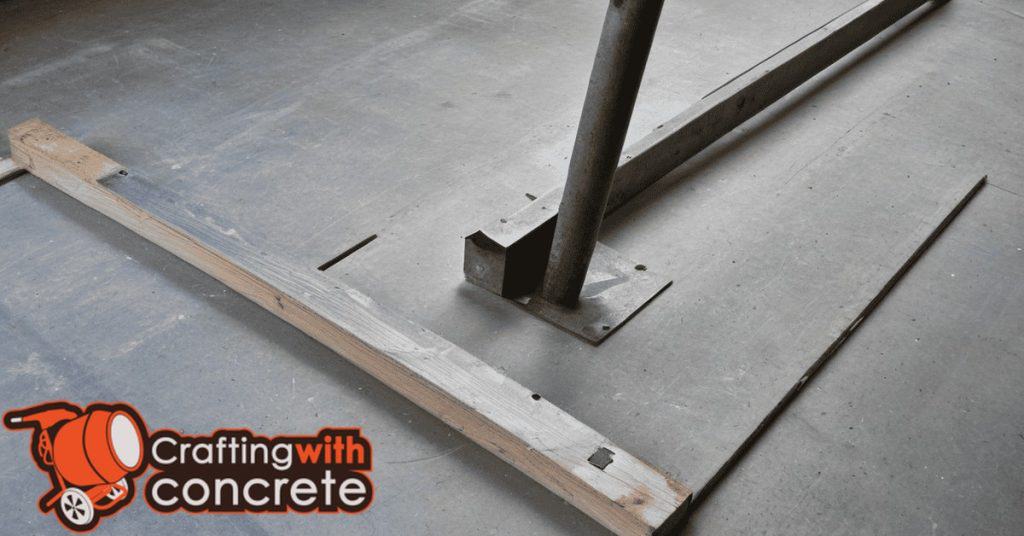
Photos, Diagrams, and Downloadable Plans
A clear photo set should demonstrate key steps from raw scrap steel prep to cutting, cleaning, forming the joint tool, welding or fastening, and a finished tool in use, with close-ups of critical angles and tolerances to guide builders. It should be complemented by diagrams and drawings, including a dimensioned schematic, labeled parts, material thicknesses, recommended cutting curves, and a simple exploded view showing assembly order. Plan for accessible, alt-text rich images, concise captions, and alt-friendly keywords, plus plan formats that are searchable and readable for technicians and hobbyists alike.
Context wise, this content supports DIYers on the jobsite by turning theory into a practical workflow, helping builders anticipate fit and alignment issues before they arise and reducing guesswork during assembly. The combination of visuals, labeled diagrams, and a one-page quick-reference guide makes it easier to verify correct construction, maintain consistent tolerances, and troubleshoot common fitment or safety questions on the fly. A lightweight “how to print and use” sidebar, a quick download CTA, and a focused troubleshooting/FAQ section help ensure practical usability while clearly addressing licensing or usage rights for the plans.
What to include in the downloadable plan
Give crews a single sheet they can use on-site. Start with clear measurements and a complete cut list — part names, quantities, lengths, and material thicknesses. Add simple templates to full scale where possible so someone can trace parts or check fit without guessing dimensions off photos or diagrams.
Include a step-by-step welding sequence and fit-up notes. Say which welds to tack first, when to clamp, when to rotate the assembly, and which joints need backing or preheat. Call out critical dimensions to check after each major step so mistakes are caught early, not after paint.
Add a short, bolded safety checklist for on-site reference: required PPE, lifting limits, hot work permit, and ventilation. Also note any special tools or consumables so the crew can verify they have what’s needed before starting. Keep it practical — crews should be able to glance at the plan and know exactly what to do next.
Example diagram callouts and photo checklist
Label diagrams where the work will actually happen: show exact join locations, fastener types and spacing, grain direction, and any clearance or tolerance dimensions. Take a clear shot of the full layout before you cut. If you skip that, you lose your reference and everything becomes guesswork.
Shoot step-by-step photos as you build: rough layout, each staged cut, dry-fit assemblies, and the finished fit. Capture close-ups of critical dimensions with a tape or ruler in frame. Always include a photo of the test cut or mock-up piece — the test-cut results prove your setup before you waste material.
Don’t forget site-condition shots. Photograph the base and supports so you can confirm level and alignment later — check base compaction and bearing points now, not after the first load. If something looks off in your pictures, fix it, retake the photo, and document the correction. No excuses.
Conclusion
With a solid scrap-steel tool in hand, you gain control over joint quality, durability, and a clean finish that holds up under concrete load and time. The payoff is safer work, fewer miscuts, and less downtime chasing replacement parts.
Make it happen by this practical flow: verify your steel and templates meet the design requirements, cut and shape parts to fit, assemble and weld using tried-and-true practices, then set up, calibrate, and field-test on a small area before larger use; document your settings for repeatability, maintain sharp edges, and keep a clean, organized work area as you go.
Common mistakes to avoid are using the wrong steel grade or thickness, skipping the appropriate heat treatment or tempering when the design calls for it, rushing welds or misaligning parts, and testing on a real pour without first trying a dry run on scrap. Always wear proper PPE, unplug tools when adjusting, keep hands and clothing clear of hot or moving parts, and test in a controlled, small area before full-scale use.
If the project exceeds the tool’s design tolerance, if you’re unsure about the heat-treating steps, or you’re fabricating in large batches and the joint quality matters for structural integrity, consider bringing in a professional. Stay focused, work deliberately, and you’ll turn scrap steel into a reliable, repeatable control joint tool you can trust day after day.
FAQ
What is a control joint tool and what does it do?
A control joint tool helps mark clean, straight joints in concrete. It makes joints consistent so cracks form where you want, not randomly. It’s a simple hand tool, not a fancy machine.
What scrap steel should I look for to make this tool?
You want flat stock or angle iron with minimal rust. Avoid thin, flexy metal that won’t hold a straight edge. If it looks bent or warped, skip it and find something solid.
How do I shape and sharpen the tool safely?
Keep a firm grip and work on a sturdy surface. Use a metal file or grinder to create a sharp, straight edge. Wear eye protection and gloves—metal shavings can cut you quick. Avoid overheating the edge while grinding and cool frequently in water if needed (but dry and re-temper if the part was heat-treated).
What are common mistakes to avoid?
Don’t rush the edge finishing. A dull edge will wander and ruin your joints. Don’t skip deburring; sharp edges snag and leave imperfections. Don’t attempt heat treatment on unknown steels—use a replaceable wear plate instead or consult a professional heat treater.