
Introduction
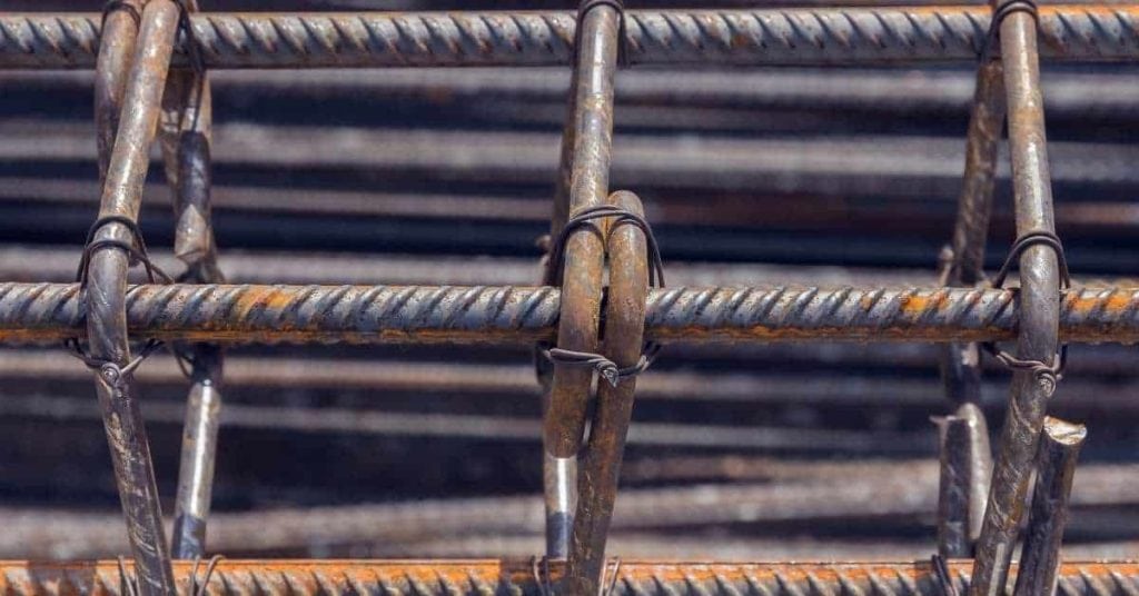
Rebar chairs, bolsters, and spacers hold reinforcement at the elevation shown on the drawings while concrete is placed. The goal is not a generic distance above the ground: it is the specified concrete cover measured from the concrete face to the nearest steel surface.
For a typical slab-on-ground, begin with the drawings, required cover, bar or mesh size, and the approved bearing surface. Then select supports that fit the reinforcement, will not sink or puncture a membrane, and can hold the assembly in position through placement.
Key takeaways
- Use the project drawings and adopted code first; slab thickness alone does not determine chair height.
- Measure cover to the nearest surface of the rebar, wire mesh, stirrup, or other reinforcement.
- Choose a chair or bolster with the correct seating geometry, load capacity, and bearing foot for the base, membrane, formwork, or mud slab.
- Get support spacing from the drawings, engineer, or chair manufacturer rather than using a universal spacing rule.
- Support and tie laps, edges, openings, joints, and thickened areas so they cannot sag or shift.
- Keep workers, hoses, buggies, and screeds off lightly supported steel; use a planned access route.
Table of Contents
- Introduction
- Key takeaways
- Why keeping rebar off the ground matters
- Types of rebar chairs, supports, and alternatives
- Material specs and standards explained
- Planning placement: spacing, layout, and sequencing
- Step-by-step installation process
- Tools and materials checklist
- Visual checkpoints and inspection guide
- Common mistakes and how to avoid them
- Maintenance, removal, and post-pour considerations
- Conclusion
- FAQ
Why keeping rebar off the ground matters
Reinforcement that bears on soil, a form, or another concrete face can lose the cover required at that face. It can also collect mud, loose scale, or other contamination that should be removed before placement. Light, tightly adherent surface rust is not automatically a reason to reject rebar; loose scale, pitting, oil, mud, or questionable damage needs direction from the project specification or engineer.
Proper support keeps the bar layout, laps, and elevation from changing under construction and concrete-placement loads. It is especially important where steel is close to the bottom of a slab, near a form edge, or in a lap zone with overlapping bars.
Cover is not a universal “2-inch” rule
Required cover varies with the element, exposure, bar size, whether concrete is cast against earth, and the governing documents. For U.S. work, the applicable edition is the one adopted by the jurisdiction or named in the contract documents; ACI identifies its structural concrete code through its ACI 318 building-code portal. Follow the drawings when they are more restrictive.
Measure perpendicular to the concrete face, from that face to the nearest reinforcement surface. Use the drawing or applicable tolerance requirement for acceptance; do not substitute a rule of thumb.
Types of rebar chairs, supports, and alternatives
Select the support by the reinforcement arrangement and the surface it bears on—not only by the nominal slab depth. Bar supports include chairs, continuous bolsters, high chairs, support bars, and spacers. CRSI’s placing guidance describes these supports as devices for attaining cover and holding reinforcement in position.
Plastic chairs and spacers
Plastic chairs are often suitable for light reinforcement when their published load rating, bar seat, height, and base are suitable for the job. Use a broad or membrane-compatible foot where required. Do not assume a pointed or narrow-foot chair can bear on a vapor barrier without puncturing it.
Steel chairs, bolsters, and high chairs
Use prefabricated bolsters or high chairs where a heavier mat, multiple mats, beam steel, or top reinforcement needs support. Confirm the chair material, finish, cover at its exposed ends, and manufacturer load/spacing instructions. Do not stack chairs or improvise height with loose blocks.
Concrete spacers and other alternatives
Commercial concrete spacers may be appropriate when specified and when their dimensions and bearing surface maintain cover. Do not use loose brick, wood, crumbling concrete pieces, mortar dabs, or stakes as substitutes on structural work. They can shift, create an unapproved inclusion, damage a membrane, or leave the reinforcement at the wrong elevation.
Material specs and standards explained
The controlling order is: structural drawings and specifications; adopted building code; the ACI 318 edition referenced by them; any specified construction and tolerance documents; then chair-manufacturer instructions. ASTM may govern a product material, but it is not a substitute for the project’s structural cover requirement.
Choose chair height from actual geometry
For a bottom mat, establish the specified bottom cover at the relevant concrete face. Set a sample chair on the actual bearing surface and place the actual bar in its seat. Measure from the bearing-side concrete face to the bottom surface of the bar. Change chair size or seating arrangement until that measured distance meets the drawing requirement and tolerance.
For welded-wire mesh, use the wire diameter and the manufacturer’s seating geometry. For two mats, establish the bottom mat first; then use the specified clear spacing, both bar diameters, and the high-chair or support-bar geometry to establish the upper mat. Check each mat from the concrete face that controls its cover. A vapor barrier, blinding layer, insulation, or membrane can change both the bearing condition and the measurement reference, so do not guess.
Match support capacity and bearing surface
Verify that the selected support can carry the assembled reinforcement and expected placement activity at the proposed spacing. Its feet must remain stable on compacted subbase, formwork, a mud slab, or an approved plate. FHWA pavement guidance specifically warns that chairs must be stable and must not sink into the base before paving; correct soft spots and use an approved bearing solution where needed.
Planning placement: spacing, layout, and sequencing
Lay out supports according to the project details, engineer’s direction, or the manufacturer’s published spacing and load data. There is no reliable universal chair spacing based only on bar number, grid size, or square footage. Increase support where the assembly is heavier or more likely to move, but do not treat “one chair at every intersection” as a general requirement.
Plan for the element you are building
- Slab-on-ground: support the mat at its specified functional elevation and protect the subbase or vapor barrier from chair feet.
- Footing or grade beam: maintain the specified bottom and side cover from the prepared base, mud slab, or forms. Concrete cast against earth is a distinct cover condition.
- Wall: use suitable spacers and ties to maintain both face covers, bar spacing, laps, openings, and any two-mat geometry against form pressure.
- Beam: bottom bars, stirrups, side bars, and multiple layers commonly need bolsters, support bars, and form-compatible spacers rather than ordinary slab chairs.
- Suspended slab: reinforcement bears on formwork; top steel typically needs high chairs or support bars. The formwork and access system must be designed for construction loads.
Support critical locations
Review edges and corners, lap zones, openings, sleeves, drains, blockouts, thickened strips, construction joints, and changes in mat elevation before setting chairs. These locations often add steel weight or restrict the available space. Tie contact laps as detailed so they cannot separate or roll, and add approved support where the assembled bars sag or the elevation changes.
Staggering supports can be useful for stability and access, but it is not a universal “shear-plane” requirement. The observable standard is simpler: the completed reinforcement must remain at its specified location during placement and consolidation.
Step-by-step installation process
- Confirm the information. Before work starts, have the approved layout, bar marks and sizes, cover requirements, laps, joints, openings, mat elevations, and any required inspection hold point. Stop if the drawings conflict with field conditions.
- Prepare the bearing surface. Complete excavation, compaction, forms, and any specified subbase, mud slab, insulation, or vapor barrier. Remove debris, standing water, and soft spots. Repair a damaged membrane using the approved method before placing steel.
- Dry-fit one support and bar. Use the actual chair, bar, and bearing surface to measure cover to the nearest bar surface. Confirm that the chair foot is stable, the bar sits securely, and the chair does not interfere with forms or embedments.
- Lay out and set bottom supports. Place chairs or continuous bolsters to the approved layout. Keep their feet fully seated. At a membrane or soft base, use only the approved support foot, plate, or bearing method; do not drive stakes through the membrane.
- Place and tie the bottom reinforcement. Set bars to the required spacing and tie intersections as needed to hold the layout. Secure laps, edges, and areas around openings. Tie wire ends should not project toward a concrete face where they would reduce cover.
- Build upper mats or cages. Install support bars, high chairs, beam bolsters, wall spacers, or other specified supports. Place the next layer and remeasure its cover and clear spacing. Do not rely on the first mat’s height to establish the second.
- Check stability. Apply light hand pressure at representative locations. Bars should not roll, chairs should remain upright, and the assembly should not sag or sink. Replace damaged supports rather than bending or stacking them.
- Set access before concrete arrives. Provide planks, walk boards, runways, or another approved load-distribution route. Do not walk directly on lightly supported reinforcement or drag pump hoses, vibrators, screeds, or equipment across it.
- Perform the pre-pour inspection. Verify cover, elevation, bar spacing, laps, joints, openings, embedments, support stability, and membrane condition. Obtain any required inspection approval before placement.
- Monitor during the pour. Assign someone to watch the steel as concrete is placed and consolidated. If a chair sinks, a bar rolls, a lap shifts, or cover is lost, pause work in that area and correct it before the concrete buries the problem.

Tools and materials checklist
- Approved chairs, bolsters, spacers, high chairs, support bars, and any membrane-compatible bases
- Specified reinforcing steel or mesh, tie wire, approved clips, and tying pliers or a tying tool
- Tape measure, cover gauge or rigid measuring block, layout string or chalk line, and level or laser where elevation control is needed
- Approved materials for membrane repair, if a vapor barrier is part of the assembly
- Planks, walk boards, or runways for the planned concrete-placement route
- Gloves, safety glasses, sturdy footwear, and rebar caps where exposed bar ends create an impalement hazard
Order chair sizes after the dry-fit measurement, not from total pour height. Bring extra approved supports of the needed type and height, plus ties and bases; do not solve a shortage with stacked or improvised materials.
Visual checkpoints and inspection guide
| Check | What to verify before the pour | If it fails |
|---|---|---|
| Cover | Measure from each controlling concrete face to the nearest steel surface at representative field locations, edges, laps, and elevation changes. | Reset the chair/support arrangement; do not pour until it meets the drawings and applicable tolerance. |
| Support bearing | Every foot is seated, upright, and neither sinking into the base nor damaging the membrane. | Replace with an approved |