
Introduction
When installing poured concrete counters, achieving the perfect height is crucial for both aesthetics and functionality. This guide will walk you through using adjustable cabinet legs to ensure your counters are level and at the ideal height.

Table of Contents
- Why use adjustable cabinet legs for poured concrete counters?
- Measuring and planning final counter height
- Choosing the right type and load capacity of adjustable legs
- Attaching adjustable legs to base cabinets: methods and best practices
- Leveling techniques and tools for precise heights
- Supporting and curing the poured concrete slab
- Anchoring and connection details: preventing shifting and separation
- Trimming legs, finishing touches, and countertop edge details
- Troubleshooting common fit, level, and crack issues
- Safety, codes, timeline, and cost estimates
- Long-term maintenance and re-leveling procedures
Introduction
Adjustable cabinet legs are your secret weapon for achieving perfect heights when installing poured concrete countertops. This guide walks you through selecting suitable leg hardware, setting the ideal height, and confirming levelness to ensure a smooth pour.
We’ve broken down the process into clear steps, diagrams, and checklists to help DIYers install safely and consistently. Where applicable, we provide actionable specs for a straightforward approach.
Why use adjustable cabinet legs for poured concrete counters
Adjustable cabinet legs offer precise height control, easy leveling, and compatibility with varying slab thicknesses to create a flush, professional look for poured concrete counters. They reduce the risk of wobble, cracking, or gaps in expansion joints by allowing fine-tuning during and after setup. Compared with fixed bases, adjustable legs accommodate uneven floors and different cabinet layouts, making a level pour more reliable and repeatable.
For DIYers and remodel projects, this means you can dial in height before pouring and avoid costly rework if the slab sits high in one area or the floor slopes. Considerations like weight capacity, base footprint, screw-in or threaded legs, and protective pads help protect floors and support a solid pour without slipping. When used with cabinet cleats, end supports, and tolerance-aware thickness planning, adjustable legs minimize future adjustments and keep the entire counter base stable through curing and usage.
Benefits over fixed cabinetry or cleats
Adjustable legs let you get the slab sitting on a solid, level platform without fighting imperfect floors. Instead of shimmed cleats that concentrate load in a few spots, legs give even load distribution under the concrete, which cuts cracking risk and keeps doors and drawers working later.
They also make leveling fast on install day. Set a rough height, pour, then turn the legs to fine-tune height and slope before the concrete cures. That saves you from chiseling or adding shims later and makes it easy to dial in appliance clearances and backsplash alignment.
What to do: pick legs rated for the slab weight, place them under stubborn support points (corners, around sinks, any long spans), and measure finished countertop and backsplash heights against appliance specs before final tightening. Don’t assume cleats will carry the load long-term—use them only as temporary holds or for non-structural backing.
When adjustable legs are essential vs optional
If your poured slab is thin — under about 2 inches — you need continuous, level support. Thin concrete will crack or sag between cabinet rails. In that case adjustable legs are not a nicety; they’re required to carry the weight and keep the pour level. Measure the slab thickness before you pour and plan supports accordingly.
Span matters. If the countertop span between solid supports exceeds roughly 36 inches, add adjustable legs at intermediate points. For spans under 24–30 inches you can often get away without them, assuming cabinets are rigid and the floor is level. Between 30 and 36 inches decide based on slab thickness and reinforcement — when in doubt, add a leg.
Site conditions change the game. If the floor is out more than 3/8 inch over 10 feet, the base is poorly compacted, or you’re removing existing toe kicks and cleats, use adjustable legs. Do a quick check: measure the span, check base compaction, and run a straightedge across the cabinets. If any of those fail, install legs now — fixing a sagging concrete counter later is a huge pain.
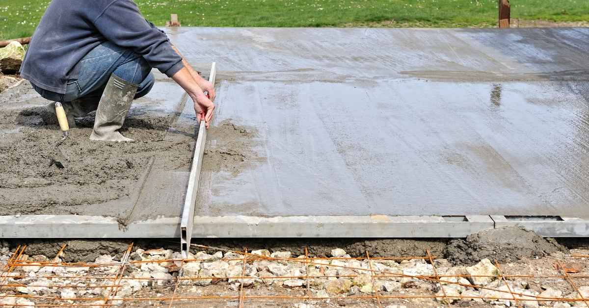
 Fresh concrete being poured over rusted steel rebar mesh for a countertop slab.
Measuring and Planning Final Counter Height
To achieve a perfect final counter height for your poured concrete counters, you’ll need to define the vertical target by considering several factors. These include the thickness of your concrete slab, backsplash height, sink and appliance clearances, and an ergonomic stance that ensures comfortable working during kitchen tasks.
Begin by creating a mounted height plan sheet outlining rough component measurements. Include contingencies for leg hardware thickness, adjustable travel, future skim coats or shims to accommodate any necessary adjustments during installation. Also consider edge treatments and backsplash effects such as overhangs, undermount sink gaps, and transitions that may impact the final height.
Accounting for Slab Thickness, Sink Lip, and Backsplash
Start with your desired finished counter elevation from the floor. Subtract the countertop slab thickness and any underlayment to find the top of cabinet box height needed. For example, if you want a 36″ finished surface and your concrete slab is 3/4″ thick plus 1/8″ adhesive, set the cabinet top roughly at 36″ – 7/8″. Always measure twice as different materials may have varying final thicknesses.
Factor in the sink type. For drop-in sinks, subtract the sink rim reveal from the cabinet height calculation to position the visible rim correctly. If undermounting, plan for the slab edge and mounting clips, allowing an extra 1/8″–1/4″ space at the cabinet top for the flange and caulk line.
Don’t forget the backsplash build-up at the wall: tile, thinset, and a backsplash slab add thickness that changes how the countertop meets the wall and upper cabinets. Mock up the final edge with scrap materials and check the fit before installation. If unsure, raise the cabinet top with shims rather than cutting it short.
Appliance and Fixture Clearances (Ranges, Dishwashers, Faucets)
Before installing the countertop, mock up actual appliance and fixture positions and measure from the finished floor and counter. Ranges typically need a thin side gap for trim—plan on about 1/8″–1/4″ each side and at least 1/2″–1″ behind for power or gas connections and ventilation clearance.
Dishwashers require room for their rails, hoses, and door swing. Leave roughly 1/4″ each side in the cabinet opening for the rails and shims, and about 1/2″–3/4″ clearance at the front so the dishwasher face and door don’t rub against the cabinet face or countertop overhang. Also allow 1″–2″ at the back for hoses and the electrical box to prevent pinching.
For faucets, check spout reach and deck-to-backsplash distance before cutting holes. A high-arc spout may need an extra 2″–4″ behind the sink center so the handle doesn’t hit a backsplash or window sill. Ensure the spout tip lands at or slightly above the sink drain center to avoid splatter or hitting a front lip.
Tolerances and Shrinkage Planning
Concrete will move after pouring, so expect a small drop during curing and additional shrinkage as the slab dries. Plan for roughly 1/16″–1/4″ of settlement in the first few weeks, with another possible shift over the first three months.
Leave an adjustment range at the cabinet legs and supports—at least 3/8″–1/2″ of vertical adjustment—to level after initial cure and again at 28 days. Do not permanently fasten or caulk critical height points until you’ve checked and re-leveled after the first week and at one month.
Before installation, check base compaction and confirm final counter height against earlier considerations (slab thickness, sink lip, backsplash, appliances). If you try to nail the height dead-on now, you’ll likely be reworking it later. Leave adjustment room, measure twice during cure, and lock things down only when the surface has stabilized.
Choosing the Right Type and Load Capacity of Adjustable Legs
When selecting adjustable legs for your poured concrete countertops, consider three main types: steel threaded leveling legs, heavy-duty leveling feet, and jack-style supports. Evaluate each based on their adjustability, ease of installation, and suitability for concrete countertops.
Crucially, assess their load ratings against the actual weight of your slab. Account for per-leg load distribution, total system load, and whether loads are dynamic or static. Always apply a sensible safety margin to ensure long-term stability and level alignment with existing cabinetry.
Calculating Weight: Slab + Sinks + Live Loads
Calculate your slab’s dead load in three steps. First, measure the footprint and thickness to find the volume in cubic feet. Then, use the formula weight = volume × 150 lb/ft³. For instance, a 4 ft × 4 ft slab at 0.5 ft thick weighs 8 ft³, equating to 1,200 lb.
Next, add the weight of fixtures like sinks. Standard kitchen sinks can range from 30–100 lb empty; water adds more if full. Weigh or check manufacturer specs for heavy stone sinks or inline equipment.
Finally, include live loads and a safety margin. Typical live loads are 40–100 lb/ft² depending on use; push higher for heavy use or storage. Divide the total (slab + sinks + live load) by the number of legs to find required capacity per leg, then add at least 25% spare capacity.
Selecting Leg Load-Rating and Safety Factor
Don’t guess on leg capacity. Divide your calculated slab weight plus sinks and live loads by the planned number of legs. Choose legs rated higher than that number, aiming for a 2–3× safety factor per leg.
Match leg rating to cabinet span. Wider runs need more legs or heavier-duty center legs to prevent sagging. Extra legs or higher-rated legs are cheap compared to a cracked slab or sagging cabinet.
Before finalizing, check leg mounting and substrate firmness. If the base isn’t solid, higher-rated legs won’t save you. Calculate load, pick legs with a 2–3× margin, and match leg rating and quantity to the span.
Corrosion-Resistant and Adjustable Range Considerations
For moisture-prone areas, choose corrosion-resistant finishes like stainless steel or zinc-plated legs. Galvanized or marine-grade stainless are worth the extra cost for wet kitchens, utility rooms, or patios to prevent rust.
Consider vertical travel needs. Measure planned slab thickness, add screed, tile, underlay, and allow for subfloor unevenness. Buy legs with at least 20–30mm more travel than that estimate for fine-tuning during installation. Insufficient travel may lead to shimmying or cutting into the slab.
Ensure your chosen corrosion-resistant option maintains required load capacity. Check base compaction and mounting details, as good legs on a soft base still fail. Pick a finish and travel that match the environment and real measurements, not just the cheapest spec sheet option.
Attaching Adjustable Legs to Base Cabinets: Methods and Best Practices
Securing adjustable legs to base cabinets involves selecting mounting options that cater to face-frame, frameless, and plywood bases. Plate-mounted legs, corner brackets, and internal cleats are used for stability or ease of installation. Each base type requires specific screw types, sizes, and spacing, reinforced by pilot holes and corrosion-resistant fasteners. Consider load ratings and reinforce with extra studs, cleats, or spreaders to prevent sag under poured concrete counters.
Understanding these options ensures level, adjustable baselines that align with sink heights and future counter-height changes, reducing call-backs and maintenance while enabling accurate height planning. It also helps plan for anti-sag measures, proper reinforcement, and quick-reference checks for uneven floors or loose hardware to maintain stability over time under load.
Mounting to Particleboard, Plywood, and Metal Cabinets
Particleboard bottoms are common but weak. Reinforce with a plywood or solid-wood block glued and screwed to the underside first, or use a backing plate/washers spread under the leg flange. Use confirmat screws or coarse-thread #8–#10 wood screws long enough to bite at least 3/4″ into the backing, always pre-drilling.
- For particleboard, use 4 × #10 × 1-1/2″ wood screws into a 3/4″ plywood patch; torque to about 8–12 ft·lb. For thicker carcass (3/4″+), use #10 × 2″ screws.
- For face-frame cabinets, use through-bolts from the leg plate into a 1-1/2″ solid block in the box, with a washer and nut inside; torque to 12–18 ft·lb depending on bolt size (usually 1/4″–5/16″).
- For metal cabinets, use M6 machine screws into captive nuts or nutserts; typical plate size 60×60 mm with 4 × M6 × 16–20 mm screws, torque to manufacturer spec (~6–10 N·m).
Plywood cabinets accept screws well. Use #10 wood screws 1-1/2″ to 2″ long into the plywood or into a glued blocking strip. If thin, add a glued-in block or a plywood patch under the leg to spread load.
Thin-gauge metal cabinets need machine fasteners. Use self-drilling sheet-metal screws for thicker gauge, or rivets/weld studs if possible. For thin metal or hollow trays, use stamped backing plates inside the cabinet or nutserts/toggle bolts. Always use the correct screw type and back it up with blocking or plates.
Spacing and Placement of Legs for Optimal Support
Legs carry weight, so place them where cabinets change or load concentrates. For standard base cabinets up to 24″ wide, legs at the two front corners (and matching rear supports) are usually fine. For single runs 24–36″ wide add a centered leg or sturdier middle bracket. For anything over 36″, use a center leg plus one or two intermediate supports.
Place legs within 2 inches of cabinet seams and joint lines, directly under sinks, dishwashers, or heavy countertop appliances. Keep spacing so there’s no more than about 24″ between legs under heavy load; for light duty you can stretch to 30–36″.
Check material where you attach legs and fasten accordingly. Do a quick level and compression check before finalizing, shimming as needed. Avoid long unsupported spans and place legs near seams and heavy loads.
Fastening to Floor vs Free-Floating Cabinets
If in a seismic zone, on a second-story, or carrying heavy appliances, anchor cabinets to floor or wall. Tie the cabinet to studs or solid subfloor so it can’t tip or slide. Err on the side of anchoring for stability.
Free-floating with adjustable legs works fine for short runs, island units, or light duty where the floor is even and cabinets are well-butted and screwed together. Make sure legs bear load evenly and check leveling and clearances; earlier sections cover leg placement and mounting details for different cabinet materials.
Leveling Techniques and Tools for Precise Heights
Begin leveling by establishing a clear datum line along the entire countertop length. Use this as your reference point to set leg heights consistently across cabinets. Employ long framing or builder’s levels, straightedges, chalk lines, and careful measuring to define target heights and ensure each section aligns with the datum.
Lock adjustable legs in place and make incremental adjustments while noting measurements. Maintain a running log of target measurements for future reference. Use a laser level for quick, repeatable checks by projecting reference planes along the run and translating laser readings into precise leg adjustments. Solo-work strategies like temporary shims, helper boards, or guide rails help maintain alignment during measurement and tightening.
Using a Laser Level and Long Straightedge Effectively
Set your laser level to project a clear, continuous reference line across the work area. Mark this line on a string or temporary batten for easy reference. Move the long straightedge to each leg location and transfer the laser height down to the leg or post.
Hold the straightedge firmly and sight along it while adjusting the leg. Repeat at both ends of the straightedge to avoid accidentally building in a slope. If shimming is necessary, keep shims thin and tucked under the bearing point. After setting heights, check for twist or bow by walking the straightedge across multiple points. Spin the laser 180° and confirm the reference line hasn’t shifted.
Shimming, Temporary Jacks, and Bracing During Pour
Support forms and cabinets on solid temporary supports before pouring concrete. Use adjustable steel or heavy-duty screw jacks with full-width plates to distribute load evenly. Check base compaction and place plywood pads under jacks to prevent sinking.
Shim only to fine-tune height once primary supports are in place. Drive hardwood or composite shims tight and trim flush, leaving at least two backup jacks in place while working. If adjusting leg heights, do so one side at a time while others carry the load, keeping a secondary support under any moved element.
Brace forms against lateral forces from wet concrete with angled shores tied back to the slab or stakes. Monitor during the pour and re-tighten jacks as concrete settles. If a support shifts, stop and re-stabilize before continuing. Transfer loads safely by staging adjustments and never taking more than one support out of commission at once.
Verifying Final Height Before Pouring
Walk the space with a tape measure and straightedge to confirm finished height against appliance and cabinet specs. Dry-fit dishwasher, sink, or use mock-up boxes to verify drain and toe-kick clearances. Check backsplash layout by holding a full-height board where counter meets the wall.
Mark control lines on walls and studs at exact finished surface height and cross-check with your laser level or long straightedge. Measure run-to-run continuity at several points along long runs to catch any low spots or steps before pouring concrete. If adjustments are needed, make them now rather than trying to fix after the pour.
Verify plumbing trap and drain elevations, and ensure electrical boxes and outlets are set back as required. Check base compaction and blocking under penetrations. If anything isn’t a clean fit, stop the pour; patching after concrete cures is expensive and ugly.
Supporting and Curing the Poured Concrete Slab
To manage hydrostatic pressure during pouring, plan temporary formwork and bracing. Anchor and brace cabinets to prevent movement. Define a curing timeline, transferring load from temporaries to permanent supports in stages.
Monitor daily for movement or cracking, maintain proper form alignment, and protect legs and cabinets with moisture barriers and seating protection. Use water curing, curing compounds, and plastic sheeting for indoor kitchens, considering heat, humidity, and cleanliness factors.
Formwork, Edge Supports, and Reinforcement Strategies
Ensure forms are square, level, and compacted before starting. For small slabs, use 2×6 or 2×8 timber forms staked every 2-3 feet at edges with overhangs. Tighten spacing to 12-18 inches for heavy loads or long cantilevers.
Use welded wire mesh or rebar (welded intersections, supported bars) in a 12-18″ grid near mid-depth. Edge reinforcement is crucial: use continuous bars or heavier perimeter mesh, add extra bars at overhangs/walls, and place support legs closer together at edges.
Bracing Cabinets and Preventing Movement During Pour
Tie cabinets together using 2×4 blocking between toe kicks. Fasten short braces from cabinet carcasses to formwork if cabinets sit against forms. Install diagonal braces to the floor or stakes outside the pour area.
Pour in controlled stages, keeping the vibrator away from cabinet faces. Check bracing after each bucket or truck; stop and re-brace if anything shifts. Use extra blocking and tighten straps when vibrating nearby.
When to Transfer Load from Temporary Supports to Legs
Concrete gains strength over time: initial set in a few hours, safe handling at 24-48 hours, full design strength at ~28 days. Before transferring loads, check for firmness, no visible deflection, steady weather, base compaction, and bearing under each leg.
Transfer loads slowly and in stages, watching for cracking or sag. Start gradual transfer at 24-48 hours for light loads, allow about 7 days for moderate loads, and wait the full ~28 days before placing heavy, continuous, or structural loads on the slab. Stop and re-support immediately if new cracks or settling occur.
Anchoring and Connection Details: Preventing Shifting and Separation
Securing poured concrete countertops to cabinet supports is crucial for preventing lateral movement, resisting shear forces at the interface, and avoiding stress cracks along edges. Employ a mix of concrete-compatible fasteners, blocking, and edge adhesives to secure the slab in place. Tailor your approach based on whether you’re working with base cabinets, wall cabinets, pre-fab supports, or traditional framing.
Under-slab blocking and continuous cleats along front and back edges are common methods that should integrate seamlessly with adjustable cabinet legs without compromising height precision. Edge adhesives—construction adhesive, epoxy, or grout—require proper surface preparation and curing considerations to minimize slip and edge creep. Plan your approach carefully as it guides reliable alignment checks, supports future disassembly or releveling, and ensures the countertop remains securely attached over time.
Fastening Slab to Cabinet Substructure
Position the slab and confirm its placement before proceeding. Level the slab and check base compaction under cabinets to prevent sagging later. Locate pre-set anchor points or embedded plates in the slab edge.
For embedded plates, drive screws into them from the cabinet side or use machine bolts through a concealed plate under the countertop. For longevity and aesthetics, use stainless fasteners into embedded plates or bolt through a concealed top plate into slab anchors. Pre-drill pilot holes in the cabinet top; avoid relying solely on short wood screws into plywood.
Hand-tighten first, then seat the slab and torque to firm, not crushing, tightness. Apply a thin bead of compatible sealant or closed-cell gasket between slab and cabinet to prevent point loads and water entry. Push and wiggle the assembly to confirm no movement before finishing joints.
Sealing Joints and Preventing Moisture Wicking
Keep water out where the slab meets cabinets by running a thin, compressible backer rod and sealing with a quality exterior-grade sealant — silicone or polyurethane sealant. Tool the joint smooth to ensure water beads off; avoid gaps or overfilling with rigid caulk that may crack upon movement.
Install continuous flashing under the cabinet front edge, lapping onto the slab and directing any seepage to the finished floor. Flashing can be metal, flexible PVC, or self-adhesive membrane. Ensure it doesn’t interfere with fasteners if you’ve already fastened the slab to the cabinet substructure.
Annually inspect and maintain joints. Replace cracked, adhered, or dead caulk. If signs of staining, soft wood, or mold appear at the cabinet toe or base, repair rot and reinstall fresh backer rod, sealant, and flashing. Neglecting this area can lead to rot later on.
Expansion Joints and Allowed Movement
Leave continuous movement gaps wherever different materials meet or long runs end: at walls, cabinet ends, through-floor penetrations, and where the slab meets fixed masonry. A good rule of thumb is about 1/8”–1/2” (3–12 mm). If unsure, err on the larger side to prevent pinching and cracking.
Pack gaps with a compressible backer rod before sealing. Push the rod to a depth that leaves the sealant bead roughly half as deep as the gap is wide. This allows room for movement without tearing the sealant or wicking moisture into the substructure.
Never create a rigid connection at expansion-sensitive spots. Use slip joints, flexible fasteners, or allow the slab to float where it crosses an expansion joint. Double-check anchoring and sealing details at every joint as they’re prone to failure first.
Trimming legs, finishing touches, and countertop edge details
Begin final trimming only after the concrete slab has reached its target strength. Plan for precise alignment with cabinet tops and toe kicks, deciding whether to trim legs, add shims, or use adjustable feet. Document measurements including overhangs and clearances for ventilation or plumbing. Prepare for toe kicks, edge treatments, and countertop overhangs, ensuring clean, waterproof transitions around the perimeter.
A consistent measuring protocol and appropriate tools prevent overcuts and misalignment. Essential tools include a saw or router for legs, a level, calipers, straightedge, contour gauge, sharp pencil, and a secure reference edge to maintain accuracy. This discipline ensures proper fit, ventilation, plumbing access, waterproofing, and a professional, durable finish.
When and how to cut legs after cure
Wait until the concrete has reached usable strength before touching the legs—at least 7-14 days, ideally 28 days for full cure. Confirm strength with manufacturer’s charts, field-cured cylinders, or a firm tap test. Before cutting, make final height decisions and mark each leg. Keep the slab fully supported while cutting in small amounts to prevent shifting or cracking.
Use a sharp diamond blade on an angle grinder or circular saw for clean cuts; an oscillating tool works for tight spots. Cut slowly with steady pressure, protecting the slab edge from chips. Support the slab throughout and stop immediately if you see cracks or movement during cutting.
Installing continuous toe kick, trim, and aesthetic covers
Fit the continuous toe kick in small sections, dry-fitting pieces and shimming as needed for a flush fit following the cabinet run. Mark and drill for hidden fasteners, attaching with short screws or construction adhesive. If legs were cut after cure, ensure those cuts still allow the kick to slide on smoothly.
Conceal leg heads and gaps with dedicated covers or trim strips. Slide covers over leg heads and snap or screw them in place, leaving removable covers for structural legs. Check base compaction and alignment before final fixing. Finish the cabinet-to-slab junction with a tight seam and matching caulk or sealant, aiming for a uniform reveal.
Integrating sinks, faucets, and appliances post-pour
After the slab and countertop set, confirm cutouts match the template before touching the sink or faucet. Measure twice at the finished height, check the sink flange sits flat, and mock-fit the bowl and faucet. If undermount, dry-clamp brackets and verify the rim clears the finished edge.
Check clearances for appliances, ensuring doors, trim, and drawer openings align with the countertop edge. Confirm supply and waste stub-outs reach where the sink will be, and check that faucets won’t hit windows or cabinets when turned full. If legs were trimmed earlier, refer back to those final height steps before locking anything down. Use manufacturer torque specs and a level when fastening the sink, sealing all seams with proper sealant and testing under running water.
Troubleshooting Common Fit, Level, and Crack Issues
Understanding common issues in fit, level, and cracks helps ensure successful installation of poured concrete counters. This guide assists in diagnosing uneven runs, gaps at cabinet faces, misaligned appliances, and toe-kick clearance, while outlining corrective actions such as releveling, reseating feet, shimming, cross-bracing, and re-anchoring to the base.
Early identification of cosmetic versus structural cracks saves time and prevents failed installs. Proper prevention—solid support under all legs, consistent leg spacing, and moisture monitoring during cure—keeps counters true for years. Pre-check layouts with a straightedge and document recurring issues for future projects to improve cabinet performance without guessing.
Fixing an Out-of-Level Run After Pour
If the run is off by less than 1/4″ over its length, start by checking base compaction and the ride height of nearby slabs. Small dips can often be corrected with under-slab shimming or thin grout lifts under low areas.
- Run ≤ 1/4″ over any length → Try localized grout lift or thin self-leveling topping (≤ 1/4″).
- Run > 1/4″ but ≤ 1/2″ over a short span (<3 ft) → Consider planing high spots or targeted grinding; confirm no underlying loss of bearing.
- Run > 1/2″ over any 6–8 ft, or slope affects appliance operation → Plan for partial panel replacement or re-leveling the cabinet support system; call a professional if multiple panels are involved.
For larger, edge-driven problems, planing the slab edge or cutting back high areas is the next step. Grind or saw down high spots until the run is true. If you find multiple high and low spots, don’t waste time patching every dip; that’s a sign you need a bigger correction.
When the error is widespread, consider replacement versus resurfacing. Resurfacing can hide minor slope issues but won’t fix structural leg height problems. If legs or supports are the cause, replace legs or adjust supports rather than dumping material on top. Refer back to earlier troubleshooting notes on cracking and settling if you suspect movement before deciding which path to take.
Addressing Cracks and Settlement
Quick check first: measure the crack width, look for offset or stair-step patterns, and watch it for movement over a week or two. Hairline cracks that don’t widen are usually just drying; larger, diagonal, or offset cracks that keep changing are likely settlement or structural.
- Hairline shrinkage cracks ≤ 0.3 mm (≈0.012″) with no displacement → Typically cosmetic; clean and seal or epoxy thin-fill.
- Crack width 0.3–1.0 mm (≈0.012″–0.04″) or minor widening but no offset → Consider epoxy injection and monitor 2–4 weeks.
- Crack width > 1.0 mm or any visible offset/step or active widening → Structural concern: stop loading, check base compaction, and call an engineer for assessment.
If the crack is a stable hairline, you can usually clean and seal it or use thin epoxy to stop moisture and staining. For wider static cracks where the slab hasn’t shifted but needs strength, epoxy injection or mechanical stitching with stainless staples and grout works well to restore load transfer.
If the slab has clear displacement, loss of bearing, or ongoing movement, plan for partial replacement of the affected panel and correct the cause: check base compaction, fix drainage, and remove poor fill. Stitching or epoxy won’t save a slab that’s sinking. And if the crack affects walls or structural loads, call an engineer before you spend money on fixes.
Preventing Moisture Damage and Rot at Cabinet Tops
Inspect the tops of cabinets where masonry or countertops meet wood. Dark stains, soft spots, or peeling paint indicate moisture wicking in. Pry up a small section of molding or run your hand along joints after rain to feel for dampness.
Fix the source first: plug gaps, direct water away, and stop leaks. Install a continuous bead of high-quality exterior-grade sealant along the joint and press a thin closed-cell backer or foam tape into larger gaps before sealing. Add a thin metal or PVC drip edge across the top front and slope any exposed top surface slightly to shed water. Use a breathable, paintable membrane or sill gasket at the wall-to-cabinet interface to block capillary action.
If wood is already soft or rotted, cut out the bad wood down to sound material and replace with pressure-treated or rot-resistant stock, then prime and paint. For quick protection on exposed tops, coat with a marine or exterior varnish for a few seasons while arranging a permanent fix. Don’t just caulk over wet wood—dry it, repair or replace the rotten pieces, then seal the gap properly so you don’t have to redo the job next year.
Safety, Codes, Timeline, and Cost Estimates
Typical Timeline from Prep to Full Cure
Day 1–2: Measure, mark, and verify base compaction. Set adjustable cabinet legs or temporary supports at exact heights before pouring. If using a subcontractor for installation, be present to confirm dimensions and check reinforcement placement against the plan. Ensure elevation, anchors, and form fit are verified before pouring.
Day 3: Form and reinforce. Place rebar or mesh as per plans and shore forms securely. Pouring and initial setting occur on the same day; expect concrete to take its initial set within a few hours. Protect new surfaces from wind, sun, and rain; cover or mist as needed. Remove shores after 24–72 hours based on load and weather conditions, but do not rush if conditions are cold or mix has high water content.
Day 4–10+: Allow light, controlled traffic in the area and make any necessary surface adjustments within the first week. Full structural loading and heavy equipment use wait until the 28-day mark when concrete reaches design strength. If unsure about timing for your specific job, cross-check with project specs or local code to avoid early overloading and potential cracking.
Concrete Mix and Curing Guidance
Target mix: Aim for a 28-day compressive strength of 3,000–4,000 psi for typical countertop slabs. For exposed or heavy-use counters, consider 4,000–5,000 psi mixes. Use a low water-cement ratio, proper entrainment for freeze-thaw climates, and include mid-depth admixtures if large panels are placed indoors where cracking is a concern.
Curing method: Prefer wet-cure (keep surface damp) for at least 7 days in temperate climates. If wet-cure isn’t practical indoors, use a curing compound applied per manufacturer instructions immediately after finishing, and cover with plastic to reduce evaporation. In cold weather (≤40°F / 4°C), maintain above-freezing temperatures for at least 72 hours and use insulating blankets; in hot weather, use windbreaks and misting to slow evaporation.
Minimum strength for load transfer: Avoid transferring significant loads until the slab reaches at least 50% of design strength — typically around 7 days with good curing. For safety, follow conservative timing: light transfers at 48–72 hours only when the slab is firm and no deflection is visible; moderate transfers after 7 days; full loading at ~28 days.
Sample Cost Breakdown and Permit Guidance
Itemized sample (typical small run, DIY labor):
- Adjustable steel legs: $40–$120 each depending on capacity and finish.
- Embedded anchor plates, fasteners, blocking: $50–$200 total.
- Concrete (materials for countertop panel only): $6–$10 per sq ft (materials-only) depending on mix and admixtures.
- Rebar/wire mesh and chairs: $1–$3 per sq ft.
- Sealants, flashing, caulk: $30–$100.
- Tools/rentals (vibrator, power float, saw): variable; plan $50–$200/day if rented.
Permits: Most jurisdictions do not require a separate “countertop” permit but will require permits when structural work, plumbing relocations, or gas connections are altered. Check local building department if you’re changing load paths, adding anchors to framing, or modifying floor framing. When in doubt, call the permit office with a brief job description.
When to Call a Pro or Engineer
- Span > 8 ft with continuous cantilevered overhangs or slabs thicker than 4″ — consult a structural engineer.
- Crack with offset > 1 mm, or crack that widens over time — stop and call an engineer.
- Evidence of bearing loss (visible settlement under legs, panel rocking) > 1/4″ — stop and call a pro to re-assess base compaction and support.
- Work altering structural framing, removing load-bearing members, or relocating heavy appliances that change load paths — hire a licensed tradesperson and pull permits.
Long-term Maintenance and Re-Leveling Procedures
Regular maintenance ensures your cabinets remain stable and safe. Inspect them quarterly for the first year, then every six months, checking for loose fasteners, wobbling, leg height changes, cracks, moisture, and corrosion. Tighten and re-level as needed to maintain level surfaces and even load distribution. Watch for signs of worsening tolerance like gaps or creaking.
This routine minimizes wobble, supports vibration control with anti-slip pads and isolation after heavy use, and ensures safe access to adjust legs in the proper order from level to plumb. Know when to replace legs or hardware, or call a professional if fasteners won’t tighten or if you detect structural concerns.
Re-Leveling Cabinets Without Removing the Slab
Begin by locating high and low points and remove toe-kick panels for access. Work one cabinet run at a time. Use a small cabinet jack or screw jack with a plywood spreader to lift corners incrementally.
Check base compaction under legs before lifting — soft or missing material needs repair or a bigger pad, not brute force. Loosen fasteners where the run meets adjacent cabinets and the wall. Place shims under adjustable legs or between the cabinet base and a solid pad. Protect plumbing, wiring, and finishes while levering.
Lift in small increments, no more than 1/8″–1/4″ per lift, re-checking level and plumb often. Never jack directly against the slab or fragile finishes. If the slab shows hairline cracking or shifts under load, stop and call a professional to avoid larger concrete damage.
Inspecting Fasteners, Seals, and Leg Hardware
Wiggle cabinets and legs to check for play. Retorque fasteners to the manufacturer’s spec (often 8–15 ft·lb for common cabinet bolts) and replace stripped or damaged heads. Reseal cracks, hardening, or gaps in sealant and caulk lines every 2–5 years using a durable, paintable silicone or polyurethane.
Inspect wooden legs for soft spots, rot, insect damage, or surface flaking. Replace if necessary. Check metal legs and brackets for pitting, corrosion, or cracking welds. Wire-brush and prime surface rust; replace hardware showing deep corrosion.
Set a schedule: check fasteners and seals annually, re-seal every 2–5 years as needed, and plan on replacing high-use or outdoor hardware every 5–10 years. If something looks wrong, don’t procrastinate — failing hardware leads to expensive fixes later.
Installation Day Checklist: A Concise 10-Step Guide
- Verify final height plan: Confirm your target heights, appliance templates, and control lines are accurate before proceeding.
- Check base compaction: Inspect the base for any soft spots. Patch or add plywood pads where necessary to ensure a solid foundation.
- Install adjustable legs: Securely attach adjustable cabinet legs using recommended plates and fasteners, pre-drilling holes and torquing as specified by the manufacturer.
- Set laser datum and adjust legs: Establish a laser datum line to ensure precise leveling. Adjust each leg to within 1/16″ of your target height across the entire run.
- Install forms, reinforcement, and edge chairs: Place and secure concrete forms, install reinforcement, and position edge chairs. Brace cabinets to forms for added stability.
- Dry-run sink and appliance mock-ups: Test fit sinks and appliances to ensure clearances are adequate before pouring the concrete.
- Pour in controlled stages: Pour concrete in manageable stages, monitoring bracing throughout. Tighten supports as needed during the pour process.
- Begin curing: Initiate your chosen curing method and protect slabs from wind, sun, and rain to maintain optimal curing conditions.
- Initial checks at 24-72 hours: Inspect the slab for any signs of distress. If firm, begin transferring load in stages.
- Final checks at 7 and 28 days: Re-check leg heights, fastenings, and seals. Once confirmed, lock permanent trim into place.
Conclusion
Achieving the right height for poured concrete counters using adjustable legs might seem mundane, but it significantly impacts safety, durability, and aesthetics in the long run. Invest time in deliberate steps now to prevent cracks, wobble, and misalignment later.
In practice, confirm your final height plan, ensure the legs are rated for the load they’ll bear, attach them according to your chosen cabinet method, level each leg using the appropriate tool, brace and cure the slab, anchor and trim as needed, test for movement, and finish with correct edge details and sealing. Follow this steady, repeatable sequence: measure, install, level, cure, anchor, trim, test, finish.
Common mistakes to avoid include underestimating load capacity or misplacing legs, skipping proper attachment to base cabinets, and rushing the pour before the slab is fully cured or level verified across the whole run. Always work with cabinet legs set and tested in a dry, controlled environment, use a level and straightedge, prevent shifting during curing, and adhere to local codes for support and anchoring. Prioritize safety by testing small changes, respecting load limits, and never pouring over unsecured or undersized legs.
If the floor is severely uneven, you’re dealing with a long, unsupported span, or you’re uncertain about anchoring details to prevent shifting, consult a professional. Clear your plan, obtain a firm estimate, and proceed only when confident the structure won’t move or crack. Maintain patience and precision for perfect-looking, high-performing counters.
FAQ
How do adjustable cabinet legs help with height for poured concrete counters?
Adjustable cabinet legs allow you to precisely set the desired countertop height before pouring. This eliminates guesswork and the need for shims that may shift over time, ensuring a consistent, reliable result.
What height should I set before pouring the concrete?
Set your adjustable legs to accommodate the thickness of your poured concrete plus any additional finish you plan on top. To ensure accuracy, stack blocks to match your desired thickness and test with a straight edge. Always measure and verify from the cabinet base up.
How do I level the legs so the counter is flat and true?
Level each leg individually using a bubble level or laser level, then lock them in place. Use a long straightedge across the front and back of your cabinets to confirm you’ve achieved a flat plane. Regularly check for level throughout the process to avoid any surprises during curing.
What are common mistakes to avoid with adjustable legs?
Be cautious not to over-tighten the legs, which could strip the threads and compromise their functionality. Assume your floor is not perfectly level; always adjust and re-check for levelness. Lastly, don’t skip a final level check after pouring, as shifts can occur due to moisture or weight.
Additional Resources & Downloadable Templates
To assist you further, we’ve prepared downloadable PDFs packed with practical information:
- Leg Plate Drilling Template (60×60 mm example): A precise guide for drilling cabinet leg plates.
- Leg Spacing Table: Recommended leg counts and spacing based on run length and slab thickness to ensure stability.
- Fastener Selection Chart: Screw/bolt sizes and part numbers suitable for common cabinet substrates, such as plywood or metal.
- Troubleshooting Decision Tree Checklist: A printable guide to help resolve any issues that may arise during the installation process.
These templates provide exact drill patterns, typical part numbers (e.g., #10 × 1-1/2″ Type 17 screw for plywood patches, M6 × 16 mm machine screws for metal cabinets), and sample layout diagrams. Adapt them to your specific cabinet configuration and local building codes.