
Introduction
A concrete pad for a generator is a level, reinforced slab designed to support the weight and vibration of a generator. This piece covers how to lay out bolts, keep proper clearance, and control cracks in a DIY-friendly way. Plan a clean, square pad with a solid base and verify level before you pour.
Before you pour, check local rules and the generator’s instructions for bolt layout and required clearances. Leave room for ventilation and service access, and plan joints or seams to help control cracks. If in doubt, rely on the label or manufacturer guidance and use sturdy forms, proper reinforcement, and clean, level footing.
Key takeaways
- Confirm generator clearance for ventilation, maintenance access, and exhaust routing.
- Choose bolt layout aligned with generator mounting holes and base footprint.
- Incorporate control joints and proper cementitious mix to limit cracking.
- Ensure subbase drainage and frost protection per local regulations and manufacturer guidance.
- Verify pad thickness and footprint fit generator dimensions before concrete pour.
- Follow curing, sealing, and safety precautions to prevent early cracking and injuries.
Table of Contents
- Introduction
- Key takeaways
- Overview and Regulatory Requirements
- Clearance, Ventilation, and Access
- Pad Footprint, Dimensions, and Thickness
- Bolt Layout and Anchor Selection
- Reinforcement and Crack-Control Strategies
- Concrete Mix, Placement, and Curing Best Practices
- Subbase, Drainage, and Frost Protection
- Tools, Materials Checklist, and Visual Checkpoints
- Conclusion
- FAQ
Overview and Regulatory Requirements
Before you pour a generator pad, check the local rules that apply to temporary and permanent structures. Look for permit requirements, setbacks, and any documentation your authority may ask for. Confirm what codes or standards typically govern pads in your area by consulting the official guidance or a qualified tradesperson.
Gather any needed approvals and keep them accessible on site. If you’re unsure, verify with the building department, utility provider, or the generator manufacturer what documentation is recommended. Always cross‑check label or data sheet instructions when planning the layout and composition.
Applicable codes, permits, and manufacturer requirements
Before you start planning your generator pad, check local building, electrical, fuel, and fire codes. These will guide you on size, height, setbacks, and safety features.
Always follow the generator manufacturer’s site and anchoring instructions. They know their equipment best and can prevent issues down the line.
You’ll likely need permits for this project. Check with your local building department to see what’s required in your area. Safety first, buddy!
Site assessment and load information to collect
To size your pad right, you need the generator’s weight, footprint, and exhaust orientation. Check the manufacturer’s specs or manual.
Consider fuel type too. If it’s liquid propane (LP) or diesel, you’ll need extra safety measures like containment sumps in case of leaks.
For the subbase, get geotechnical data if needed. This could be soil strength tests to ensure your pad won’t sink over time. It’s worth the investment for a solid foundation.
Clearance, Ventilation, and Access
Define the clearances around the generator and pad to allow for cooling and service access. Plan orientation to avoid obstructing doors, vents, or exhaust routes on the equipment. Check that the chosen location can accommodate future maintenance needs as well.
For exact distances and access requirements, refer to the generator’s installation instructions or manufacturer guidelines. If you’re unsure, label the clearance figures from the spec sheet and double‑check with local rules or your utility for any interference considerations. Verify any fire or setback requirements with the building department before final placement.
Clearances from structures, openings, and combustibles
Safety first. Your generator pad needs space to breathe. Check your manufacturer’s guidelines and local codes for exact clearances.
Structures: Keep the pad at least 5 feet away from any buildings or walls. This gives you room to work and prevents exhaust fumes from backing up into living spaces.
Openings: Stay 20 feet away from windows, doors, and vents. Fumes can travel and you don’t want them inside your home.
Combustibles: Keep the pad at least 10 feet away from flammable materials like wood piles or propane tanks. Safety is key here.
Exhaust routing and ventilation considerations
The generator’s exhaust needs a clear path out of the area. Don’t let fumes build up or backdraft into your home.
Exhaust direction: Position the pad so the exhaust blows away from structures, not towards them. A good rule is to have the exhaust point at a 45-degree angle from any building.
Inlet/outlet locations: Make sure nothing blocks the generator’s air intake or exhaust. Keep these areas clear for proper airflow and safety.
Service access, lifting, and removal space
You need room to work on your generator and get it in and out if needed. Plan for this upfront.
Maintenance: Leave at least 3 feet of clearance around the unit for routine maintenance tasks like oil changes or filter replacements.
Lifting equipment: If you ever need to lift the generator, ensure there’s enough space for a crane or other lifting equipment. This could be 10-15 feet depending on your setup.
Removal: Plan for future replacement by leaving enough room to move the old unit out and bring a new one in. This could be 20-30 feet, so consider this when choosing your pad location.
Pad Footprint, Dimensions, and Thickness
Estimate the pad length and width based on the generator footprint and the needed surrounding space. Include room for access and drainage within the planning area. Decide on a thickness that supports the weight and local soil conditions, without relying on guesswork.
When in doubt, consult the generator manufacturer’s documentation or an on‑site structural reference to determine appropriate dimensions. If you can’t find a value, consider a conservative range and plan for field verification during formwork setup. Always confirm bearing and edge distances with the spec sheet or local building guidance.
Determining pad footprint and offsets
The first step is to measure your generator’s base plate dimensions. This is the minimum size your concrete pad needs to be.
Next, add manufacturer-recommended clearance around all sides of the generator. This space allows for easy maintenance and access.
Finally, account for formwork by adding a small perimeter around your pad. A 2-inch offset is typical, but it can vary depending on your chosen formwork system.
Thickness and bearing requirements
The thickness of your concrete pad depends on the weight of your generator and local soil conditions. Don’t guess; check manufacturer guidelines for their recommended pad thickness.
Also, consult with a geotechnical engineer or use local building codes to determine your area’s required bearing capacity. This ensures your pad can safely support the generator’s weight without settling.
As a general rule of thumb, residential pads are typically 4 to 6 inches thick, but this can vary based on specific load and soil conditions.
Edge details, chamfers, and elevated curb options
Chamfers: These are beveled edges that can help prevent tripping hazards. They’re typically 45-degree angles with a depth of 2 to 3 inches.
Raised Curb/Drip Edge: A raised edge around the pad’s perimeter can help contain water and debris, keeping your generator clean and dry. This is especially useful in areas with heavy rain or snowfall.
Elevated Curb: In some cases, you might want to elevate one side of the pad to facilitate drainage away from structures. Always consider local building codes and manufacturer recommendations when deciding on edge details.
Bolt Layout and Anchor Selection
Start by marking hole locations that align with the generator mounting pattern. Transfer those marks accurately to the pad form or cured slab using a chalk line or template. Choose anchors suitable for the pad material and environment, and plan for access to fastening points during setup.
Use the generator instructions or manufacturer data to verify bolt patterns and embedment depths. If you’re unsure about the right anchor type, check product labels or installation manuals and consider alternative anchors approved for the concrete you’re using. Keep a clean, repeatable process for hole transfer from the generator to the pad.
Cast-in vs. post-installed anchors and selection criteria
When it comes to anchors, you’ve got two main types: cast-in-place and post-installed.
Cast-in-place are set before pouring concrete. They’re great for high loads as they embed deep into the pad. But they need precise installation during concrete placement.
Post-installed anchors go in after the concrete’s cured. They’re flexible, but may not handle heavy loads like cast-in-place. Choose based on your generator’s weight and manufacturer recommendations.
Bolt pattern transfer and template setup
Before you pour, set up a precise bolt pattern using the generator’s template. Here’s your checklist:
- Check template dimensions: Ensure it matches your pad size.
- Align template to pad layout: Mark out bolt locations accurately.
- Verify elevation: Make sure bolts will be at the right height for the generator’s feet.
- Check anchor embedment depth: Ensure anchors go deep enough into the pad.
- Mark bolt centers: Use a mason’s line or laser level for precise marking.
- Drill pilot holes (if post-installed): Drill through template to guide anchor installation.
- Check manufacturer specs: Ensure your pad design meets their requirements.
- Double-check layout: Walk around, check angles, and ensure everything’s square.
Quick rule: If you rush this step, you’ll end up with a poorly fitting generator or weak anchors.
Corrosion protection and torque/spec verification
For exterior pads, specify corrosion-resistant hardware. Stainless steel or galvanized bolts can save you trouble down the line.
Always follow manufacturer’s torque and tension specs. These ensure your anchors are secure and won’t loosen over time. Check their tech docs for exact values.
Verify specs on-site: Use a torque wrench to tighten bolts to the correct spec. This ensures your generator stays put, even in harsh conditions.

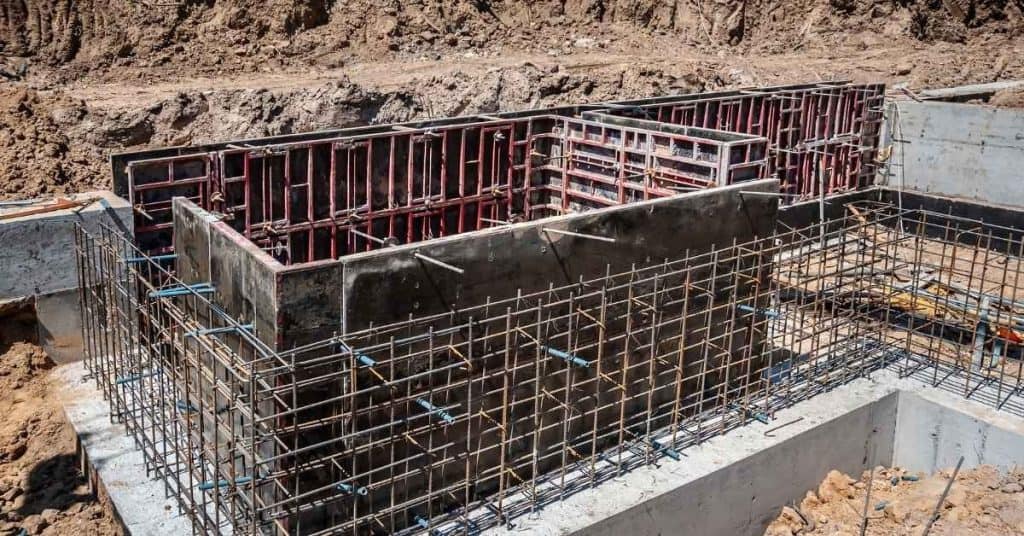
Reinforcement and Crack-Control Strategies
Decide on reinforcement to control cracking and meet load demands. Place rebar or mesh where practical, following local practice and the structural plan. Plan jointing or control joints to guide cracking in predictable locations.
Document reinforcement sizes and spacing by consulting structural notes or the project’s plan set. If you’re unsure, verify with the engineer or the concrete supplier’s guidance and adapt as needed. Use proper placement to align joints with the loader and exhaust exposure direction.
Rebar, Welded Wire Mesh, and Fiber Reinforcement Pros and Cons
The choice of reinforcement greatly impacts crack control and load distribution in your concrete pad. Here’s a rundown of the main options:
Pros
- Rebar: High strength-to-weight ratio, versatile for various designs.
- Welded Wire Mesh (WWM): Easy to install, provides good crack control in two directions.
- Fiber Reinforcement: Enhances flexural strength, controls micro-cracks, and improves durability.
Cons
- Rebar: Labor-intensive installation, can lead to cold joints if not properly lapped.
- WWM: Limited crack control in the direction of the wire orientation, less flexible for complex designs.
- Fiber Reinforcement: Lower strength than steel, may require additional reinforcement for critical areas.
Choose your reinforcement based on design loads and exposure. Rebar is ideal for high-load applications, WWM works well for flat slabs, and fibers are great for improving durability in harsh environments.
Control Joints and Isolation Techniques
Controlling where cracks form is key to maintaining the integrity of your concrete pad. Here’s how:
Control Joints: Saw-cut these into the slab after it reaches initial set, spacing them at 10-15 times the slab thickness (max 6 ft). This encourages cracks to form where you want them.
Isolation Techniques: Around penetrations and adjacent structures, use expansion joints or isolation strips. This prevents stress transfer and stops cracks from propagating into other structures.
Timing is crucial: cut control joints before the concrete starts cracking naturally (around 24-72 hours after pouring).
Proper Reinforcement Placement and Cover
Maintaining specified cover is vital to prevent corrosion and spalling. Here’s how:
Cover: Use chairs or spacers to maintain the required concrete cover over reinforcement (usually 2-4 inches). This protects steel from fire, impact, and moisture.
Placement: Keep reinforcement away from surfaces to minimize the risk of corrosion. For slabs, place rebar at least 1 inch from the top surface and 3 inches from the bottom. For walls, maintain a 2-inch clearance from both sides.
Consistency: Maintain consistent cover throughout the pad. Inconsistencies can lead to differential corrosion and spalling.
Concrete Mix, Placement, and Curing Best Practices
Choose a concrete mix appropriate for outdoor use and the expected load. Prepare the subbase and formwork before placing, and keep the space free of debris. Place in manageable lifts to avoid cold joints and settlement issues.
Follow curing recommendations from the mix producer or local standards to prevent early shrinkage or surface cracking. If exact curing times or conditions aren’t known, check the label, supplier sheet, or manufacturer instructions and plan a curing window accordingly. Maintain moisture or coverings as required for the climate.
Mix selection, admixtures, and strength guidance
Choosing the right concrete mix is crucial for your generator pad’s longevity. Start by confirming the required compressive strength with your project specs or manufacturer. Most residential generator pads require a 3000-4000 psi mix.
Consider using admixtures to enhance your concrete’s properties:
- Air entrainment: Improves durability by creating tiny air bubbles that help resist freezing and thawing damage. It’s a must in colder regions.
- Water reducers: Lower the water-cement ratio, increasing strength without changing the mix’s proportions.
After pouring, curing is vital to develop your concrete’s full strength. Follow manufacturer guidelines or consult local codes for minimum cure durations.
Placement, consolidation, and finishing techniques
Proper placement and consolidation ensure a strong, durable pad. Pour the concrete in lifts no thicker than 8 inches to avoid overworking.
Consolidate each lift using a vibrating screed or immersion vibrator to remove air pockets and achieve full compaction:
- For small pads, use an immersion vibrator to ensure thorough consolidation around anchors.
- Larger pads may require a vibrating screed for efficient leveling and consolidation.
After consolidating, finish the surface with a bullfloat or power trowel to achieve the desired flatness. Be careful not to overwork the concrete, which can lead to excessive bleeding and weaken the pad.
Curing timeframes and weather protection
Concrete gains most of its strength during the first few days after pouring. Protecting it from extreme temperatures and moisture loss is crucial for proper curing:
- Moisture retention: Keep the pad moist using a sprinkler, wet burlap, or plastic sheeting for at least 7 days, following manufacturer guidelines.
- Temperature control: Protect the concrete from freezing temperatures and excessive heat. In cold weather, use insulated blankets or heating systems. In hot weather, provide shade and keep the pad moist.
Consult local codes or an engineer for minimum cure durations specific to your region’s climate. Allow at least 28 days before applying any significant load to the pad.
Subbase, Drainage, and Frost Protection
Prepare a stable subbase with proper compaction and drainage considerations. Ensure the surface drains away from the generator and any nearby structures. Address soil conditions that could affect pad performance over time.
For frost protection and soil concerns, review local guidance or manufacturer recommendations on subgrade preparation and insulation needs. If you’re unsure, verify with a local concrete supplier or building official and choose a practical drainage solution. Plan for access to water flow paths and avoid ponding around the pad.
Granular Subbase Design and Compaction
A solid, well-draining granular subbase is crucial for your concrete pad. It improves bearing capacity and drainage, preventing water from seeping into the soil.
Use clean, angular materials like crushed stone or gravel with a minimum particle size of ¾ inch. The subbase should be at least 4 inches thick, but follow geotechnical guidance for your specific site conditions.
Compact the subbase in lifts, no more than 3 inches deep each time. Use a plate compactor or vibrating roller to achieve at least 95% maximum dry density. Verify with a nuclear densometer if possible.
Surface Grading and Drainage Detailing
Proper surface grading ensures water doesn’t pond on your pad or flow towards buildings. Provide a minimum slope of 1/8 inch per foot away from structures.
Install drip edges around the pad’s perimeter to direct water away from the structure. Use metal flashing or rigid insulation with a sloped top surface.
Create drainage channels using aggregate or trench drains if needed. Ensure they’re connected to a proper stormwater management system.
Frost Depth, Insulation, and Mitigation Options
In cold climates, frost heave can damage your pad. Check local building codes for minimum frost depths. In areas with severe freeze-thaw cycles, consider deeper footings or insulation.
Insulate the pad’s perimeter using rigid foam board or similar materials. This helps prevent frost from penetrating and heaving the soil.
For slab-on-grade construction in cold regions, use thickened edge slabs with increased reinforcement to resist frost heave. Consult a geotechnical engineer for site-specific recommendations.
Tools, Materials Checklist, and Visual Checkpoints
Assemble a practical tool list and have materials staged for the day’s work. Include formwork, rebar or mesh, anchors, bonding agents, and finishing supplies. Set up a simple on‑site checklist to track progress and safety steps.
During setup, perform visual checks for plumb, level, and alignment relative to the generator. Verify that all required components are present and that hole locations match the mounting pattern. If any item is uncertain, reference the label, manual, or local code guidance and adjust before proceeding.
Tools and equipment to have on hand
Before you start your concrete pad project, make sure you have all the necessary tools and equipment. Use this checklist to ensure you’re well-prepared.
- Tape measure: To accurately measure and mark out your pad dimensions. Check it against a known size to confirm its accuracy.
- String line and stakes: For setting out the perimeter of your pad. Ensure the string is taut and level for precise layout.
- Shovel: To dig and prepare the base of your pad. Check the depth against your project plans to ensure it’s correct.
- Rake (garden or hard rake): To level and compact the base material. Use a straight edge to confirm it’s flat.
- Level: To check the base and pad surface for proper slope and finish. Use a 2′ or 4′ level for best results.
- Concrete forms (wood, metal, or plastic): To contain your concrete. Check they’re secure, square, and plumb before pouring.
- Vibrator (internal or external): To remove air bubbles from the concrete. Test it before use to ensure it’s functioning correctly.
- Concrete saw: For cutting expansion joints and making clean cuts in the pad surface. Check its blade for nicks or dullness before use.
Quick rule: Always check your tools and equipment before starting work to avoid delays and rework.
Materials and specification checklist
Before you start mixing or pouring, use this checklist to verify your materials. It’s crucial to ensure everything is up to par to avoid costly mistakes.
- Concrete Mix: Check the batch ticket for the mix design (e.g., 3000 psi, 4000 psi). Confirm it matches your project’s requirements. Wrong mix can lead to weak concrete.
- Cement: Verify the cement is within its expiration date and has been properly stored. Old or improperly stored cement can cause weak concrete.
- Aggregates (Rock, Sand): Check for proper gradation as per your mix design. Incorrect aggregates can result in poor workability and strength.
- Admixtures: Ensure you have the correct admixtures (if any) and they’re within their shelf life. Wrong or expired admixtures can affect concrete’s properties.
- Reinforcement Bars: Check bar sizes and lengths against your plans. Incorrect reinforcement can lead to structural issues.
- Anchors/Bolts: Verify you have the right type, size, and quantity of anchors or bolts for attaching items to the concrete.
- Sealer: If using a sealer, check it’s compatible with your concrete mix and has been stored properly. Wrong or improperly stored sealers can affect their performance.
- Formwork Materials (Plywood, OSB, etc.): Inspect for damage or warping that could transfer to the finished surface. Damaged formwork can result in a poor finish.
Quick rule: Always check materials against your project plans and specifications. Skipping this step can lead to expensive rework or structural issues down the line.
Visual checkpoints and measurement tolerances
Use this checklist just before pouring to ensure everything is set for a successful pour. It’ll help you catch issues early and avoid costly rework.
- Template Placement: Check that the formwork template is correctly positioned according to your layout plan. Confirm by measuring from known reference points.
- Elevation: Verify that the top of the forms are level and at the correct elevation using a laser level or water level. Tolerance: ±1/4″ (6mm).
- Flatness: Ensure the base of the formwork is flat to prevent concrete from flowing out. Use a straight edge and feeler gauges to check for any high or low spots.
- Joint Locations: Mark joint locations on the forms before pouring. Check that they align with your layout plan and are at the correct spacing (typically 24″ – 36″ apart).
- Anchor Alignment: Inspect anchor bolts to ensure they’re properly aligned, plumb, and at the right elevation. Tolerance: ±1/8″ (3mm).
- Formwork Tie Holes: Verify that all formwork tie holes are clean and free of debris to prevent blockages during concrete placement.
- Reinforcement Inspection: Check that reinforcement bars are properly placed, aligned, and at the correct spacing as per your plans. Ensure they’re not blocking concrete flow paths.
- Subgrade Preparation: Inspect the subgrade surface to ensure it’s clean, compacted, and free of any debris or soft spots that could cause formwork movement.
Quick rule: Always double-check your measurements against your layout plan. A few minutes spent verifying can save hours of rework later.
Conclusion
A solid concrete pad for the generator hinges on proper footprint, bolt layout, crack control, and sound curing. Do the prep right, keep it dry and square, and you’ll avoid costly repairs, noise, and movement down the line.
First, verify the regulatory requirements and clearance, then mark the pad footprint with correct dimensions and thickness, lay out bolts in the right pattern, prepare subbase and drainage, and plan for ventilation and access before you mix, place, and cure with care, testing along the way with visual checkpoints to confirm everything is true and solid.
Common mistakes to avoid are skipping the subbase or frost protection, undersizing or misplacing anchors, using the wrong concrete mix or poor curing, and neglecting proper ventilation and access clearances. Stick to the safety rules: keep work area dry, use proper PPE, test a small area if you’re unsure, and don’t rush curing or edging. If any step feels off or you lack clear code guidance, slow down and call a professional before you proceed.
If the situation calls for it—unclear frost depth, heavy loads, complex drainage, or electrical/code concerns—get a pro involved. With careful planning and deliberate steps, you’ll have a durable, safe pad that serves the generator reliably for years. Stay sharp, stay safe, and finish strong.
FAQ
How should I mark and verify the bolt layout on the footing before pouring concrete?
mark the bolt locations clearly on the form. Check that each bolt is level and straight, and verify alignment with the generator mounting holes using a simple template or string line. If anything looks off, correct it before you pour and recheck with the manufacturer’s mounting instructions.
What should I do to maintain proper clearance around the generator after pouring and during operation?
Leave space around the unit for airflow and access for servicing. Confirm you can reach the shutoff, fuel and exhaust areas, and any maintenance points. If the pad will be under the generator, recheck clearance after pour and according to the unit’s instructions and local guidance.
How do I plan for crack-control joints and reinforcement around anchor bolts?
Place any reinforcing near the edges and around the bolt area as specified by the plan or manufacturer. Use control joints to target typical crack paths, and ensure the joints don’t line up with bolt pockets where they could cause concrete to crack. Always verify with the product instructions or a qualified adviser.
If I need to modify the pad after pouring, what’s safe to do?
Avoid cutting, grinding, or chiseling hardened concrete near the bolts unless you have a solid plan and correct safety gear. Seek guidance on acceptable post-pour modifications from the concrete supplier, the generator manufacturer, or local rules. If in doubt, don’t proceed until you’ve checked the labels and instructions.]