
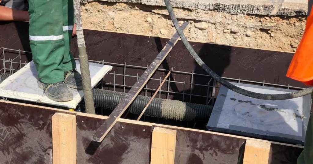
Rebar or wire mesh is in the right place only when its type, layout, laps, concrete cover, and elevation match the approved drawings—and when it is firmly supported so it stays there during placement. Steel that was visible before the truck arrived is not necessarily steel that will function where the design intends.
Rebar lying on the subgrade, welded-wire reinforcement resting on a vapor retarder, or bars pressed against forms are warning signs when the drawings require those materials to be elevated or kept clear. The needed correction may be simple before the pour, but it should be based on the project documents rather than a generic rule found online.
This is an inspection guide, not a reinforcement design guide. Get the current structural drawings, reinforcing notes, approved revisions, and any required inspection instructions before moving steel or deciding that a discrepancy is acceptable.
Key Takeaways
- Correct reinforcement placement is three-dimensional: bar or mesh type, spacing, laps, cover, and elevation all matter.
- Steel on the ground is not automatically acceptable simply because it is inside the forms.
- Chairs, bolsters, and other suitable supports must hold the assembly without sinking, rolling, or allowing broad spans to sag.
- Check more than one location, especially edges, corners, overlaps, openings, thickened areas, and travel paths.
- Assign someone to watch the reinforcement during concrete placement, not just before it begins.
- Do not improvise lap splices, bar substitutions, repairs, or structural corrections when the approved detail is unclear.
- If hardened concrete hides a suspected placement problem, a qualified professional may need to assess records and use appropriate non-destructive locating methods.
ToC
- How to Tell if Rebar Is Actually in the Right Place
- Why Position Matters: Steel Present Is Not Steel Working
- Preparation: Build an Inspection Plan Before the Concrete Arrives
- Pre-Pour Check: Inspect the Reinforcing Cage or Mat From Bottom to Top
- Keep It There During the Pour: A Placement-Monitoring Method
- What You Found Determines the Fix
- Common Failure Points That Make Steel End Up on the Ground
- Final Go/No-Go Checklist and When to Call for Help
How to Tell if Rebar Is Actually in the Right Place
The drawings define what “right place” means. They may show reinforcing bars by size and spacing, welded-wire reinforcement by type and sheet layout, added bars at openings, dowels between placements, or reinforcement at a particular face of a wall, beam, footing, or slab. Notes and specifications may also establish required concrete cover, lap locations, support requirements, and inspection hold points.
For a useful field check, verify five things together:
- Specified reinforcement: The installed bars, mesh, mats, dowels, or other reinforcement are what the documents call for.
- Layout and spacing: The steel runs in the correct direction, at the intended spacing, with required added pieces in place.
- Laps and anchorage: Overlaps, hooks, bends, connections, and dowels follow the detail rather than being arranged for convenience.
- Concrete cover: There is the specified concrete thickness between the steel and the bottom, sides, ends, and exposed face of the member.
- Elevation and stability: The steel sits at the intended depth and will remain there while people, tools, concrete, and vibration act on it.
A slab-on-ground may use welded-wire reinforcement or bars principally for crack control, while other slabs, footings, beams, and walls may rely on reinforcement for structural resistance, continuity, or both. That difference affects the design intent, but it does not mean crack-control reinforcement can be left wherever it lands. If the documents require it at a particular level, it must be supported at that level.
Do not use universal online dimensions for cover, chair spacing, lap length, or bar position. These depend on the member, exposure, reinforcement, concrete placement method, and governing requirements. The relevant values are the ones on the approved project documents.
Why Position Matters: Steel Present Is Not Steel Working
Concrete is strong in compression but comparatively weak in tension. Reinforcement is placed where a design expects tensile forces, crack movement, restraint, or load transfer to occur. Moving it away from that intended zone can reduce the benefit the detail was meant to provide. The extent of any effect depends on the structure, loading, actual movement, and design—not just on a tape-measure reading from one location.
Cover matters as well. Concrete around reinforcement helps provide bond and protection. Too little cover can leave steel vulnerable to moisture and contaminants, particularly where concrete faces soil, weather, or deicing-salt exposure. Over time, corrosion can expand, crack the concrete, and cause spalling. Steel tight against a form face or bearing on the base may not have the cover shown by the detail.
Position can change surprisingly quickly. Workers walking across unsupported mesh can press it down. A hose dragged through fresh concrete can pull bars sideways. Concrete placed in a concentrated heap can force a light mat downward or overturn supports. Rakes and vibrators used carelessly around steel can move it as well. None of these actions proves a defect occurred, but each is a reason to inspect and monitor.
Later cracks do not prove that reinforcement was misplaced. Cracking has many possible causes, including restraint, shrinkage, curing conditions, jointing, support movement, loading, and mix or finishing issues. This article is about confirming placement while it can still be observed and corrected, not diagnosing every crack after the fact. For general care of finished surfaces, see concrete maintenance basics; structural concerns need a separate evaluation.
Preparation: Build an Inspection Plan Before the Concrete Arrives
Most reinforcement problems are easier to prevent than to fix during a busy placement. Start by gathering the current drawing set, reinforcing schedule or notes, written revisions, and permit or special-inspection requirements. Do not work from an old phone photo if a revised drawing set exists.
Walk the forms and identify each reinforcing zone before steel obscures the view. Typical zones include the slab field, thickened edges, footings, beams, wall faces, openings, joints, transitions in thickness, and locations with sleeves, drains, anchor hardware, or added bars. Marking reference points on forms can make later checks more consistent.
Confirm what is actually being installed. Deformed bars, welded-wire reinforcement, prefabricated mats, dowels, and fibers are not interchangeable unless the design specifically says they are. Fibers may be part of a specified system, but they are not a field substitute for conventional reinforcement merely because they are available.
Have inspection tools ready before the delivery arrives:
- Current drawings and a written pre-pour checklist
- Tape measure and a straightedge or other repeatable depth reference
- Suitable chairs, bolsters, ties, and tying tools approved for the application
- A marker, clipboard, and camera for documenting checks and corrections
- A placement-access plan for workers, wheelbarrows, pump lines, screed routes, and tools
Do not assume that compacted base, a vapor retarder, bricks, wood scraps, loose pieces of concrete, or jobsite debris are acceptable supports. A support has to suit the exposure and placement conditions and hold the reinforcing assembly at the documented height. Substituting materials because they are nearby is a poor pre-pour decision.
If an authority, third-party inspector, or design professional must inspect reinforcement, schedule that visit early enough to make corrections. Once the concrete truck is waiting, the pressure to accept an unresolved detail becomes much harder to resist. Planning concrete quantity and delivery timing also helps prevent rushed decisions; use a separate concrete yardage calculation before finalizing the pour.
Pre-Pour Check: Inspect the Reinforcing Cage or Mat From Bottom to Top
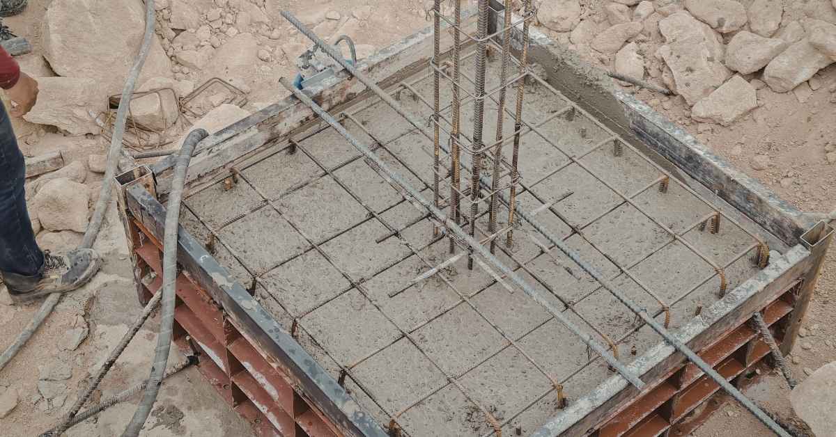
Begin with the layout, then work through support and cover. It is better to inspect systematically than to stand back, see steel in the forms, and assume the job is ready.
Check the layout and continuity
Compare the installation with the drawings. Verify bar direction, spacing pattern, mesh-sheet orientation, required extra bars, bends, dowels, and reinforcement around openings and changes in section. Where practical, count bars or sheets rather than relying on a quick glance. Look carefully where plumbing, sleeves, joint materials, or late form changes may have forced a piece out of position.
Check that laps occur where shown, pieces overlap as specified, and tied intersections or other required connections have not separated. A tie keeps pieces together; it does not prove the correct lap length, elevation, or cover. Bars that were moved for access and then retied may still be in the wrong location.
Check supports before checking depth
Press lightly on representative areas without walking across unsupported steel. The reinforcement should not rock, sink into the base, or sag between supports. Inspect supports near edges, around laps, at changes in thickness, and at locations likely to receive foot traffic or hose traffic. A support arrangement that looks adequate at the perimeter can still leave the middle of a mesh sheet unsupported.
For welded-wire reinforcement, perimeter support is particularly misleading. The sheet must be supported through the area where the detail requires it to remain. A sheet that starts flat on the base with a plan to “pull it up” later is vulnerable to ending up low, uneven, or damaged by traffic.
Measure cover and elevation from a consistent reference
Use the project’s specified cover requirements and a consistent datum: the forms, the prepared base, a known top-of-concrete reference, or another reference identified by the detail. Check the bottom and sides as well as the top relationship. At an edge or wall, look for steel that has drifted against the forms. At a slab, confirm that uneven base preparation has not changed the actual relationship between the reinforcement and the finished concrete thickness.
Take measurements at multiple representative locations. One favorable measurement does not establish the condition across a slab or cage. Give extra attention to corners, edges, overlaps, thickened portions, openings, transitions, and routes where crews will work.
Also check clearance from joint materials, sleeves, drains, embeds, and form hardware. Reinforcement should not accidentally foul a planned joint or prevent an embedded item from being installed as detailed.
Photograph the completed layout before the pour. Include wide shots that establish location, close shots of supports and unusual details, and photos showing a tape or reference where helpful. Good records do not turn a noncompliant detail into an acceptable one, but they can document what was checked, what was corrected, and who approved a change.
Keep It There During the Pour: A Placement-Monitoring Method
A pre-pour inspection only confirms the starting condition. Assign one person who understands the drawings to watch the reinforcement during placement and give that person authority to call for a pause. This is especially important for thin mats, congested work, edges, openings, footings, and other structural zones.
- Use a controlled placement sequence. Avoid building a large pile that must be dragged across the reinforcement. Place in a sequence that lets the crew fill the forms while observing what happens to the steel.
- Protect access routes. Plan where people, wheelbarrows, hoses, rakes, and screeds will travel. Use project-appropriate access methods rather than making workers balance on unsupported mesh or repeatedly walk directly on it.
- Watch the first covered areas. As concrete begins to cover the mat or cage, look for chairs that overturn, sink, or get dragged. Check that bars have not been pushed to a form face or lifted from their intended zone.
- Use placement tools for concrete, not steel adjustment. Rakes, vibrators, and similar tools should consolidate and distribute concrete according to the placement plan. They should not be used to shove reinforcement toward an assumed position.
- Recheck before access disappears. Review edges, thickened sections, laps, dowels, openings, and other critical details while they can still be reached safely and without damaging the work.
Trying to hook buried mesh and lift it after concrete has been placed is not a dependable replacement for proper pre-support. Some projects may have a documented method for handling a particular product or detail, but that is not a universal field technique. Follow the plans, specifications, and product data where applicable.
Do not rely on universal limits for vibrator use, drop height, or allowable traffic. Those conditions depend on the mix, member, equipment, crew, and project requirements.
What You Found Determines the Fix
| What you find | Appropriate next step |
|---|---|
| Concrete has not been placed, and the documented requirement is clear. | Restore the bars or mesh to the shown position, add or reposition suitable supports, retie as needed, then measure and inspect again before release. |
| The required cover, lap, elevation, or reinforcement schedule is unclear. | Stop and obtain direction from the responsible designer, engineer, building official, or qualified inspector. Do not select a rule of thumb. |
| Bars are cut, bent, damaged, heavily contaminated, substituted, or relocated at a structural detail. | Get design-professional direction. Do not invent a field splice, weld, added bar, or repair detail. |
| Placement has begun but the area is still accessible. | Pause work, verify the condition against the documents, and correct it only under appropriate qualified direction before continuing. |
| Concrete has hardened and the steel location is uncertain. | Review photos and project records, then consider qualified non-destructive investigation if the answer matters to safety, compliance, or repair decisions. |
Post-pour locating tools can be useful in suitable conditions. A cover meter, scanner, or ground-penetrating radar survey may help locate reinforcement and estimate cover, but no tool automatically verifies every detail. Results can be affected by thickness, congestion, aggregate, moisture, access, calibration, and operator interpretation. Such methods may not establish bar size, lap quality, bond, corrosion condition, or exact location everywhere in a member.
For a suspected structural slab, footing, foundation, retaining wall, or wall, do not treat an overlay, drilled holes, added bars, or demolition as a standard DIY repair. A confirmed significant deviation needs a repair decision from the engineer of record or another qualified professional. Readers working with formed walls can review the general workflow in this concrete retaining-wall guide, but wall reinforcement details must come from the design.
Common Failure Points That Make Steel End Up on the Ground
- Unsupported mesh: It is laid flat on the base with the expectation that it will be lifted later.
- Inadequate or unstable supports: Chairs or bolsters allow sagging, rollover, or sinking into uneven, muddy, or easily punctured surfaces.
- No traffic plan: Workers, tools, hose lines, and wheelbarrows repeatedly cross the steel.
- Concentrated concrete placement: Concrete is dumped in heaps and dragged across the mat.
- Late-stage conflicts: Plumbing, sleeves, forms, or joint details are completed after reinforcement installation, followed by unrecorded relocation.
- A shallow inspection: The check confirms that steel exists but never verifies support, elevation, cover, or stability.
- No pour monitor: Nobody is responsible for observing the steel once placement begins.
These are common risks, not proof of a defect on any particular project. Their value is preventive: if you can identify the likely ways steel may move, you can arrange supports, access, and supervision before wet concrete makes correction difficult.
Final Go/No-Go Checklist and When to Call for Help
Release the pour only when all of the following are true:
- The current approved drawings and reinforcing information are on site.
- Reinforcement type, layout, direction, spacing, and added details match those documents.
- Required laps, ties, dowels, bends, and connections are complete.
- Specified cover and elevation have been checked from a consistent reference at representative locations.
- Supports are stable, suitable for the application, and adequate to prevent obvious sagging or displacement.
- Steel is clear of forms, joints, sleeves, drains, and embeds as detailed.
- The crew has a planned access route and a named person monitoring reinforcement during placement.
- Measurements, corrections, photographs, and approved deviations have been documented.
Pause the pour if steel is on the base where elevation is required, is against a form, cannot be measured reliably, lacks stable support, differs from the drawings, or has been damaged or altered. Call the responsible designer, engineer, building official, or qualified concrete inspector for structural members, uncertain requirements, suspect laps or anchorage, and post-pour concerns that cannot be resolved from approved documents.
Local permit and special-inspection requirements vary. This framework helps you perform a disciplined placement check; it does not replace the approved construction documents, required inspection, or engineering judgment.