
Introduction
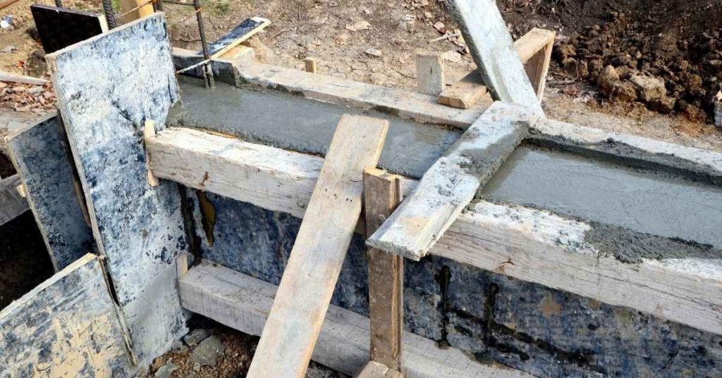
Bracing tall forms against hydrostatic pressure means preventing movement and failure by anchoring and tying the forms securely. This introduction walks you through practical checks you can do on site, without heavy jargon or guesswork. Keep the focus on stability, simplicity, and safety as you set up supports.
Before you pour, check that your braces and supports will resist the expected water load without bowing. Think about riser spring supports and how the height of a water column affects the pressure on forms, and verify compatible guides. Always confirm your approach with the product labels, manufacturer instructions, and local rules, and adjust for any site specifics.
Key takeaways
- Follow scope and safety limits; § 35.203 Equivalent facilitation applies in multi-competitor scenarios.
- Assess hydrostatic pressure rise with form height; higher water column increases load.
- Check riser stability; use dedicated braces and anchorage to resist tipping.
- Evaluate bracing options with clear pros and cons; avoid over-reliance on quick fixes.
- Apply EJMA-style guides for spacing and guides; verify with manufacturer instructions.
- Plan expansion joints and flexible connections; label critical joints for inspections.
Table of Contents
- Introduction
- Key takeaways
- Scope, Safety Limits, and When to Call an Engineer
- How Hydrostatic Pressure Varies in Tall Forms and What Drives It
- Structural Stability and Common Failure Modes for Tall Vertical Forms
- Bracing Systems and Support Options — Pros, Cons, and Practical Limits
- Guides, Spacing Rules, and Applying EJMA-Style Guidance to Tall Forms
- Expansion Joints and Flexible Connections for Tall Vertical Systems
- DIY Design Check: What to Calculate, What Tables to Consult, and Visual Checkpoints
- Testing, Commissioning, Maintenance and Common Mistakes to Avoid
- Conclusion
- FAQ
Scope, Safety Limits, and When to Call an Engineer
Define the DIY scope with clear boundaries. Specify which bracing tasks for tall forms are appropriate for a competent DIYer and which require professional analysis, including hydrostatic load scenarios and form configurations. Set explicit safety limits and trigger points that influence risk and the need for engineered input. Outline a pre-work decision framework with mandatory site clearance, utility locate, and inspection of form stiffness and fastener compatibility.
Outline the criteria for calling an engineer, such as unusual soil bearing or high hydrostatic pressures, nonstandard forms, or proposed changes to wall height or bracing that fall outside code norms. Compile a practical documentation and planning checklist that covers design assumptions, load estimation method, brace spacing, allowable deflections, installation sequence, and a contingency plan for field deviations. Present a simple risk assessment and decision flow that guides whether DIY work is appropriate or professional review is warranted, including escalation contacts and expected turnaround considerations.
When DIY is appropriate
A DIY approach can work for simple, small-scale projects. Here’s when:
Small height: Keep it under 8 feet (2.4 meters). Anything taller needs professional analysis.
Limited fluid head: If water pressure isn’t too high, you might DIY. But remember, even a small increase in water level can significantly boost hydrostatic pressure.
Reusable commercial form systems: These are designed with safety factors and can be used within their specified limits. But always check the manufacturer’s guidelines first.
Required permits, standards, and documentation
Before you start, make sure your project is up to code:
Check local building codes: Your city or county will have specific rules. Don’t guess; look it up.
Permits: You’ll likely need a permit for any significant construction work. Check with your local permitting office.
Applicable standards: Follow manufacturer instructions, industry guides (like ACI 347 or ACI 356), and relevant ASTM standards. Keep all documentation on hand in case of inspections.
Equivalent facilitation and accepted alternative methods
Sometimes, you might want to use alternatives to standard bracing. Here’s how:
Principle of equivalent safety: Any alternative method must provide at least the same level of safety as the standard approach.
Document your rationale and verify equivalence with manufacturer data or an engineer. This could be through calculations, lab tests, or field demonstrations.
Accepted alternatives: Some examples include using different materials (like fiber-reinforced polymers instead of steel), adjusting brace spacing, or using proprietary systems designed for specific applications.
How Hydrostatic Pressure Varies in Tall Forms and What Drives It
Define the vertical hydrostatic pressure profile in a filled tall form and explain how pressure grows with depth, so the top, middle, and bottom see different loads. Identify the primary drivers such as fluid head, early and late-age concrete rheology, temperature effects, and pour rate, and describe how these interact with formwork and bracing needs. Include time-sensitive considerations for when peak pressures occur during pour and initial set, and how temperature rise or cooling influences pressure evolution.
Connect the pressure variation to bracing design checks by translating a height-dependent pressure profile into wall loads, allowable deflections, and joint requirements. Offer practical decision points on what measurements or assumptions to use, such as slump, temperature, and head height, and how to document these design checks for inspections or permits. Include simple calculation notes or visual aids to help readers reference pressure versus height and safe margins in practice.
Pressure profile and key influencing factors
The pressure in a tall form filled with concrete increases as you go deeper. This is due to the weight of the liquid concrete above, known as fluid head.
Concrete’s characteristics like slump and consistency also play a role. Fresh, fluid concrete exerts more lateral pressure on forms than stiffer mixes.
Pour rate matters too. A fast pour can increase pressure by pushing concrete into place quickly. Vibration during the pour can also change how much lateral load the formwork feels.
Thermodynamics, temperature effects, and setting behavior
Temperature affects concrete’s fluidity and lateral pressure. Warmer concrete stays fluid longer, increasing the time it exerts high pressures on forms.
The heat of hydration – the warmth generated as concrete sets – can also raise temperatures. This can cause a second peak in pressure after the initial set.
Curing time matters too. Early-age concrete is weaker and more prone to excessive deflections under load. Adjust your bracing or pour schedule accordingly, especially for tall forms.
Structural Stability and Common Failure Modes for Tall Vertical Forms
Describe failure modes unique to tall, slender formwork, including buckling, bowing, deflection, and overloading of anchors. List observable symptoms during the pour such as movement, cracking at joints, or excessive wobble, and explain how these cues signal risk. Evaluate data on anchorage system integrity, covering tie spacing, embedment, fastener quality, and redundancy, with inspection steps before and during the pour to prevent sudden failures.
Assess formwork stiffness and geometric stability by examining panel thickness, spacer stiffness, bracing patterns, and the role of gussets or cross-bracing. Examine load paths and water pressure management, noting how hydrostatic pressure travels through the form and where drainage or relief provisions matter. Define deflection and settlement criteria with practical measurement methods and a plan for immediate action if limits are reached, plus troubleshooting steps for signs of anchor pullout or damaged edges and the recommended course of corrective action.
Buckling, Lateral Deflection and Slenderness Concerns
Tall, slender formwork panels can buckle or deflect under hydrostatic pressure. This happens when the unsupported length between supports is too great.
Imagine a long, thin rod. If you push it in the middle, it bends. The same thing happens to formwork panels. They bend, or buckle, under pressure.
To prevent this, use intermediate supports like walers and ties. These reduce the effective unsupported length of the panel, making it stiffer and more resistant to buckling.
Typical Failure Modes and Visual Warning Signs
During a pour, keep an eye out for these signs of impending formwork failure:
Rapid deflection: If the forms are moving or deflecting more than expected, stop the pour immediately.
Tie rod stretch: Check tie rods regularly. If they’re stretching too much, it’s a sign that the forms aren’t stable enough.
Anchor pullout, seam opening, or unusual sounds could indicate failure. Any leakage is a sure sign to stop the pour and inspect the forms.
Bracing Systems and Support Options — Pros, Cons, and Practical Limits
Establish when tall-form bracing is needed for hydrostatic pressure, tying it to target height, pour rate, and concrete mix considerations. Compare core bracing options, including frame braces, dead anchors, spring supports, and distributed anchors, with concise pros and cons on installation speed, hardware complexity, load capacity, reusability, and impact on form geometry. Define selection criteria and decision factors such as site access, worker safety, reuse after stripping, maintenance needs, and compatibility with waterproofing details.
Identify practical limits and failure modes, such as the maximum feasible height, allowable deflection, groundwater scenarios, anchor pullout risk, and redundancy requirements. Outline a practical workflow with recommended sequencing, inspection checkpoints, required fasteners and tooling, and a short field-checklist or decision tree to guide on-site adjustments as conditions change.
Spring supports: function, advantages and limitations
Spring supports are designed to absorb movement and reduce peak anchor loads. They work by compressing or extending under pressure, allowing for some flexibility in your formwork.
Advantages: Spring supports can help prevent overstressing of anchors and form ties. They’re particularly useful when you expect some deflection due to wind, temperature changes, or uneven settling.
Limitations: While they absorb movement, spring supports aren’t meant for continuous pours at great heights. For tall forms, consider using them in combination with other bracing methods. They also require regular inspection and maintenance to ensure they’re functioning properly.
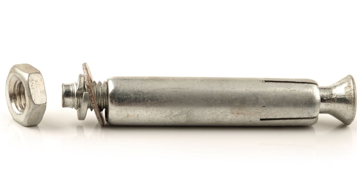
Anchor types, tie-back geometry and brace layout basics
Planning your anchor types and brace layout is crucial for tall-form bracing. Use redundant lines of support to distribute loads evenly.
For anchors, consider using a mix of deadmen (temporary earth anchors) and chemical anchors depending on your site conditions. Ensure clear bearing to structural elements or temporary deadmen to maximize their effectiveness.
Tie-back geometry: Plan your brace layout with clear tie-back angles – typically around 45 degrees from the vertical. This helps distribute loads effectively and prevents overstressing of individual anchors.
Cost-effectiveness and selection guidance
When choosing a bracing system, consider both initial equipment cost and ongoing labor and maintenance needs. Cheaper systems may require more time to install or maintain, increasing downtime risk.
Balance budget and safety: While it’s tempting to go for the cheapest option, prioritize safety. A well-designed, slightly more expensive system can save you from costly repairs or even injuries down the line.
Consider reusability too – if you’re planning multiple pours, investing in a high-quality, reusable system might be worth it. Always weigh these factors against your specific project needs and budget.
Guides, Spacing Rules, and Applying EJMA-Style Guidance to Tall Forms
Define the function of guides in formwork as restrictors of lateral movement, control sway, and maintain alignment under hydrostatic pressure. Specify required guide spacing, alignment tolerances, and attachment methods to ensure effectiveness. Translate pipe or riser guidance principles to tall concrete formwork by explaining how guidance systems prevent bowing, keep forms plumb, and manage dynamic loads during pour and cure.
Explain why EJMA and expansion joint guidance matters for tall forms, focusing on the relevance of expansion joints and bellows concepts to accommodate movement, temperature effects, and differential settlement. Provide a practical placement and spacing plan with starting distances for guides, guidance on continuous versus intermittent use, and how to handle corners and non-uniform load zones. Outline inspection steps and validation checks, including pre-pour alignment verification and post-pour rechecks for restraint-induced cracking risks, plus a compact design-check checklist to verify compatibility with manufacturer recommendations and project targets.
What pipe guide rules mean in practice
Pipe guides help prevent buckling by dividing tall forms into shorter, stiffer sections. Each section acts like a short column, reducing the risk of lateral deflection under hydrostatic pressure.
Guide stiffness matters. Stiffer guides resist bending and maintain form alignment better. Attachment method also plays a role – secure, rigid attachments transfer loads effectively and minimize movement.
Key takeaway: Use short guided spans with stiff, securely attached guides to minimize buckling risks in tall forms.
Practical guide spacing and floor-penetration reality
In real-world scenarios, floor penetrations can act as guides, helping to restrict form movement. However, relying solely on them might not be enough, especially in tall forms under high hydrostatic pressure.
Additional independent guides or lateral supports may be necessary. Always refer to EJMA and vendor data for precise guide spacing based on your specific formwork system and project conditions.
When in doubt: Consult manufacturer guidelines and consider supplementary guides or supports to ensure adequate bracing.
Expansion Joints and Flexible Connections for Tall Vertical Systems
Present flexible connectors suitable for tall vertical forms, such as bellows, braided hoses, and looped hoses, with regard to hydrostatic loading, displacement, and temperature variability. Note where each option excels or falls short for formwork and temporary risers. Map the functional trade-offs, including movement control, leak risk, installation time, ease of alignment, and how connector choice affects hydrostatic paths and form stability.
Tie these choices to code and standards considerations relevant to DIY work, such as tolerances, inspection accessibility, and practical limits on expansion joint sizes in tall forms. Provide practical selection guidelines on joint length, contraction and expansion ranges, mounting hardware, and torque limits. Outline installation and inspection steps, including pre-pour verification of clearances, mock runs, secure routing of hoses, continuous leak testing, and post-pour resilience checks under expected loads.
Bellows vs flexible hose vs braid-loop: trade-offs
When choosing a flexible connector for your tall vertical forms, consider these trade-offs:
Bellows are compact and can handle high pressure. They need minimal guiding but bear heavy anchor loads. Expect limited movement capacity and regular maintenance.
Flexible hoses offer good movement capacity and require less guiding than braid-loop types. However, they may kink or pinch under high pressure and need careful routing.
Braid-loop hoses provide excellent movement control but demand precise alignment and more guiding. They’re less prone to kinking and have lower anchor loads compared to bellows.
Where and how to place expansion joints
Placing expansion joints strategically helps control movement and reduces concentrated anchor loads:
Place joints at regular intervals, usually every 5-10 stories, depending on building height and material properties. Consult the joint manufacturer for specific recommendations.
Position joints near midspan of floor slabs to minimize accumulated movement and avoid concentrated loads on anchors.
Verify placement with the joint manufacturer to ensure it aligns with their design and installation guidelines, maintaining tight tolerances for optimal performance.
DIY Design Check: What to Calculate, What Tables to Consult, and Visual Checkpoints
Identify and quantify hydrostatic loads by determining form height, wall thickness, concrete pour rate, and assumed groundwater head to estimate the pressure on the tall form. Reference and compare to credible tables for formwork pressure and anchor capacities from manufacturers, standards, or field manuals, noting the units and applicable conditions. Plan brace layout and support choreography by sketching brace positions, spacing, and types, including attachment points to the formwork and to the underpinning or ground.
Establish pre-pour and in-pour inspection criteria, checking alignment, plumbness, brace tension, connector integrity, panel gaps, and any signs of movement; specify inspection cadence and the responsible person. Create a DIY-safe decision tree that flags thresholds triggering professional review or postponement, such as missing bracing or exceeded table values. Emphasize documentation with a one-page design check sheet that records loads, table citations, anchor capacities, layout sketch, and the inspection checklist for records and accountability.
Inputs to get from standards and manufacturers
Before you start designing your tall form bracing, gather these inputs to ensure accuracy and safety.
- Formwork lateral pressure charts: From manufacturer’s literature or standards like ACI 347. Check for air vs. water pressures, initial vs. curing stages.
- Anchor working loads: Consult vendor data sheets. Consider both tension and shear capacities.
- Expansion joint specs: Get dimensions, load ratings, and installation instructions from the manufacturer.
- Concrete mix design: Obtain slump, air content, and aggregate size distribution to estimate concrete’s self-weight and pressure.
- Pour rate: Ask your supplier for typical pour rates. Slower rates need less bracing.
- Concrete temperature: Consider both ambient and concrete temperatures during the pour. Higher temps increase pressures.
- Groundwater/water head assumptions: Estimate hydrostatic pressure from groundwater or water heads behind the form.
- Form dimensions: Measure form height, wall thickness, and panel sizes to calculate loads accurately.
Quick rule: Missing or incorrect inputs lead to under-bracing, causing form failure.
Visual and instrumentation checkpoints during pour
Regularly inspect your tall forms during the pour to catch any issues early.
- Panel deflection lines: Mark lines on form faces at critical heights. Check for bulging or bowing.
- Anchor creep: Monitor anchor movement. Excessive creep may indicate insufficient bracing.
- Leak paths: Inspect for water leaks around anchors, walers, or panel joints.
- Alignment and plumbness: Check form alignment and verticality at regular intervals during the pour.
- Brace tension: Tighten braces as needed to maintain proper tension.
- Connector integrity: Ensure all connectors remain secure and undamaged.
- Panel gaps: Check for any widening gaps between form panels.
- Movement signs: Look for any signs of movement, such as shifted formwork or displaced braces.
Quick rule: Early detection prevents small issues from becoming major problems.
Testing, Commissioning, Maintenance and Common Mistakes to Avoid
Describe pre-pour validation and mock-ups, including creating scale or full-size bracing trials to verify panel alignment, joint clearances, brace placement, anchor details, and access for inspection. Confirm that reusable components fit without binding and that bracing paths avoid interference with pour location or access. Outline a hydrostatic testing protocol using water or approved fluid, specifying target deflections and leak-detection procedures, along with instrumentation needs and a documentation plan for results.
List commissioning checks before, during, and after a pour, such as tightness, bracing redundancy, shim or spacer integrity, and form alignment. Include routine maintenance for reusable systems like corrosion checks, fastener wear, gasket condition, and storage practices, plus a schedule for component refurbishment. Identify common mistakes such as excessive bracing torque or misaligned panels, explain the consequences, and offer corrective practices. Emphasize keeping a clear log of mock-ups, test results, sign-offs, maintenance events, and revision history for future pours.
Pre-pour mock-up, trial pour and monitoring plan
Before you pour at full height, test your form bracing with a small-scale mock-up or staged pour. This helps validate pressure assumptions and lets you fine-tune your monitoring methods.
Why bother? A mock-up catches issues early, saving time and materials. It’s like a dress rehearsal for your big pour.
Here’s how:
– Build a small version of your form with bracing.
– Apply pressure using water or air.
– Monitor deflection and movement.
– Adjust your design as needed.
Maintenance, post-pour inspection and reuse notes
After removing the forms, inspect and maintain reusable components to keep them in top shape for future pours.
- Check form alignment: Ensure panels are straight and true. Misaligned forms cause leaks and weak concrete.
- Inspect bracing: Check braces for damage or wear. Replace if necessary.
- Examine anchors: Inspect anchor bolts and welds. Tighten or replace as needed.
- Check springs/guides: Ensure they’re functioning properly. Replace worn-out parts.
- Drain water: Remove any trapped water to prevent rust and damage.
- Clean components: Remove concrete residue and dirt for proper storage.
- Document findings: Keep a log of inspections, repairs, and maintenance for future reference.
- Store properly: Protect equipment from the elements during storage.
Quick rule: Regular maintenance extends your form’s lifespan and ensures consistent results.
Conclusion
Keep the focus on safety, durability, and a clean finish. If you brace tall forms correctly, you prevent leaks, misalignment, and costly damage—and you keep the project looking right as you pour or strip forms.
First, confirm the project scope and safety limits, then review bracing options and practical limits, check spacing rules and joints, plan the testing and commissioning steps, and finally outline maintenance and common mistakes to avoid. Do this in sequence, and verify each item before moving on.
Avoid these mistakes: skimping on proper bracing or ignoring load paths, skipping small-area tests before full-scale use, and forcing systems to work with loose joints or mismatched connections. Safety rules to follow are simple: don’t stand under tall forms when bracing is incomplete, re-check any temporary supports after significant adjustment, and document every check so a future owner understands the setup.
If loads are uncertain, if you see movement, or if the system doesn’t align with the guidance you’ve reviewed, call a professional. It’s smart to step back and get a second pair of eyes on the design before you push ahead. Stay methodical, test in a small area first, and you’ll finish strong with a safe, solid result you can stand behind.
FAQ
Do riser spring supports help with tall forms, and how do I know if I need them?
Riser springs can reduce the load on the main bracing by absorbing movement. Check the load rating on the spring hardware and ensure it matches the expected pressure and movement in your setup. If in doubt, compare to the manufacturer’s installation instructions and local guidance for riser supports.
How does the height of water pressure affect brace design on tall forms?
Hydrostatic pressure increases with height, so brace stiffness and spacing must account for the expected pressure at the top of the form. Use only the values from the form’s plan and manufacturer guidance, and verify against your own measurements on site.
What about expansion joints in riser systems and where should I place them?
Expansion joints or flexible connections help handle movement between risers and supports. Place them where vertical movement or temperature changes are expected, and follow the joint manufacturer’s installation directions and any applicable local rules.
Are there specific pipe guides or EJMA-related details I should follow for tall form risers?
Pipe guides and EJMA-style thinking can help keep risers aligned and reduce vibration. Check the guide manufacturer instructions and any local requirements for guide spacing, alignment, and maintenance. If you can’t find clear specs, document a safe spacing plan and confirm with a competent supervisor or engineer.